17
At reaching the pre-set speed, torque is cut back. The low torque is set to a rate, compensating the friction, for the
most part, caused by the belt and by air drag of the wheel.
Torque reduction is accomplished by lowering the voltage supplied to the motor with an AC controller, located on the
Integrated Display board. Using semiconductor devices, this novel AC controller provides arc-less switching for a long
service life.
Unbalance measurement is carried out with reduced torque at slightly in- or decreasing speed of the main shaft,
hence avoiding pendulum oscillations in the motor.
Measurement speed can be held within set bounds to any length of time by varying the motor torque. Detecting the
speed via the incremental encoder B8, speed control is implemented in software by varying the pulse-duty factor
to the AC controller. Subsequently, the already reduced voltage supplied to the motor is varied by 5% (dual-mode
control).
With more than 150 RPM of main shaft speed, the torque capacitor CT is switched o• by relay under program control.
With increasing speed, the e• ect of CT on torque drops and reactive current increases.
Direction of rotation of the main shaft is appointed by the order of wires attached to its connector.
3.13 BELT TENSION
With the drive system, belt tension is crucial as it has great in! uence on friction.
Friction can hinder extended measurement runs, e.g. service code C63. If friction uses up more energy than supplied
to the motor during prolonged measurement, the speed will drop and measurement will be stopped. During a normal
balancing cycle (10 revolutions) with a wheel clamped on, the e• ect of friction will hardly be noticed. Before the speed
reduction becomes signi" cant, unbalance data collection is completed and the brake is turned on. Excessive belt
tension puts extra load on the ball bearings and can reduce measurement accuracy.
With the belt too slack, it will slip causing premature wear and in most cases, disturbing squeaking noises as well.
3.14 BRAKING BY REVERSING THE MOTOR TORQUE
For this economical and robust brake with well-controlled torque, just the relay K4 had to be added to the drive
system.
After reaching standstill of the main shaft, motor voltage has to be switched o• immediately.
With the semiconductor AC controller, this is accomplished easily.
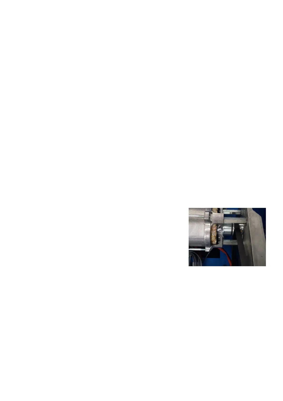
3.15 THE ELECTROMAGNETIC BRAKE
Once the balancer reaches a low RPM the Main Processor looks for the outside
weight position. Once this location is known the Processor sends a command
to the Power Supply Board to turn on the Electromagnetic brake. The Power
Supply board sends 150VDC to the Electromagnetic brake on the motor stopping
the tire and wheel assembly at TDC for the outside weight location. Once the
weight is applied the operator can then press the “F” button, this sends the
command to the Main Processor which in turns sends a command to the Power
Supply Board to rotate the motor. The Main Processor then sends a command
to the Power Supply Board to engage the Electromagnetic brake. The Power
Supply Board sends 150VDC stopping the tire and wheel assembly at TDC for
the inside weight location.
CAUTION! There is line voltage at the brake solenoids.
3.16 2D SAPE (SEMI-AUTOMATIC-PARAMETER-ENTRY)
SAPE stands for Semi Automatic Parameter Entry and this balancers is equipped by 2D SAPE ARM.
The function of this module is to:
- measure the off set of the rim reference point.
- measure the diameter of the rim at the rim reference point (2D-extension)
- apply the stick-on weights in position.
Every time the machine powers on, the software automatically checks the SAPE system in its initialization
procedure. The SAPE’s must be in the HOME position during start up. If the SAPE is good the machine
enters idle state as normal. If for example, the distance, diameter or width gauge fails, the machine displays an error
message.
The potentiometers plug into the main processor at connection X5 (Distance) and X4 (Diameter). The potentiometers
are supplied with 3.3VDC from the Processor Board. As the SAPE is pulled out and up towards the wheel the
voltage(s) change. The distance from the balancer to the wheel is generated from the voltage output and the diameter
of the wheel is generated from the amount of voltage output when the arm is moved up. Adjustment are made using
the C80/C81 service code, this procedure can be found later in this manual.