16
main shaft, oblong Light Emitting Diode (LED). Behind a second lens, there are four light detectors on an integrated
circuit.
The light of the LED is re• ected back to the encoder by one of the 256 mirrors of
the polygon ring, focused by the lens on the four detectors. During rotation of the
main shaft, the mirrors or bars will tilt and de• ect the light across the detectors A,
A`, B and B`. With further rotation in the same direction, the light will hit the next
mirror or bar, and with a full revolution, it will be de• ected 256 times across the
detectors in the above given sequence.
The light detectors A and A` respectively B and B` are connected to one ampli• er.
The di• erence in brightness between the detector pairs determines the current
state of the output channels A and B. To keep the signals A and B free from
interference, an integrated circuit ampli• es the signals.
An intended irregularity in the arrangement of the mirrors is detected with the
main shaft rotating at constant speed, serving as absolute reference. On detection of the reference, the position
counter is set to zero thus providing absolute angular position of the main shaft.
Checking the incremental encoder is via service code C74.
The surface of the ring has to be clean and shiny. If the ring is not clean, the machine will not work correctly.
IMPORTANT: Before replacing the vibratory system due to suspected encoder ring malfunction try cleaning the
encoder band. Please note: Do not use any cleaning agent (no alcohol, etc.) to clean the plastic polygonal ring!
The red LED of the re• ective encoder IC does not light up immediately after power on, since voltage is applied under
program control!
In the very unluckely event that you will discover a defective polygon ring, the complete vibratory assembly has to be
exchanged. The main shaft cannot be removed from the vibratory tube, as the ball bearings are glued-in.
Non-volatile memory at Optoencoder unit Beside the EEPROM on the Controller board, there is a second non-volatile
memory soldered to the Optoencoder unit. Both EEPROMs should hold the same data: machine model, adjustment
data, counts of counters, selected modes of operation and stored error-codes.
Having two non-volatile memories becomes bene• cial when the Controller board or the electronic box has to be
replaced.
With service code C86, the contents of the EEPROM 2 on the Optoencoder unit can be copied to the EEPROM 1
located on the Controller board, without having to set the machine model via C47 or having to perform a calibration.
On power up self-test, the contents of the EEPROMs are compared. If di• ering but valid data is detected, C85 “Copy
contents of the EEPROM on the Controller board to the Optoencoder unit” is displayed.
Do not un-plug connector X6 with power connected. A di• erence in memory contents of the non-volatile memories
may occur!
3.12 MOTOR DRIVE SYSTEM
Description: The primary functions of the motorised drive
system are to accelerate the main shaft, with the wheel clamped on it, up to the measurement speed, keeping the
speed constant during measurement and subsequently slowing down
to a dead stop. Acceleration and deceleration should be rapid but
with controlled torque, avoiding slippage of the wheel on the adaptor.
During unbalance measurement, no vibrations should be generated
by the drive system.
With some variants of the vibratory assembly, the drive motor is used
for breaking as well.
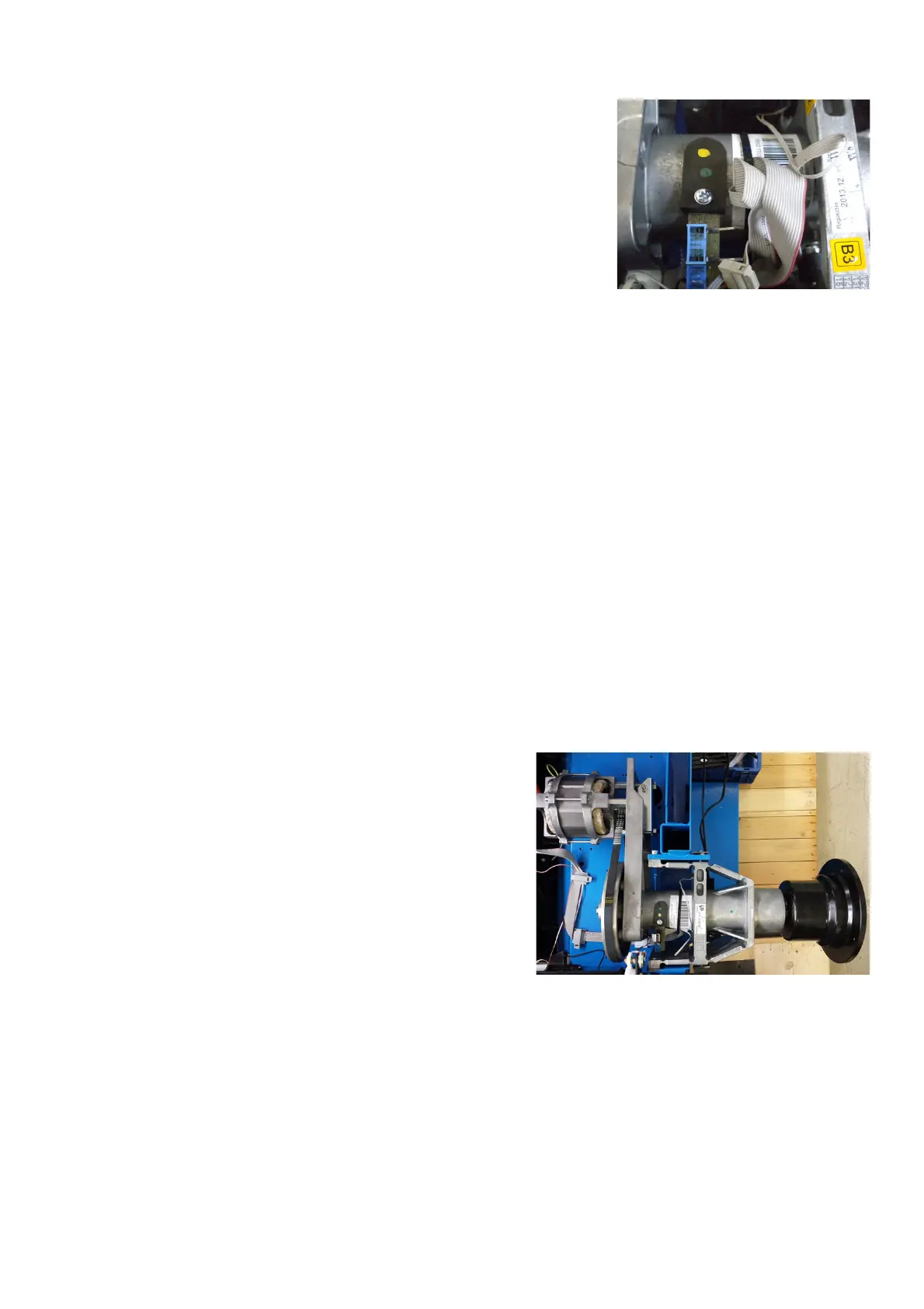
The drive system consists of the motor fastened to a bracket, secured
to the vibratory tubing. The small pulley at the motor, the big pulley at
the left end of main shaft and the multi-V belt as well. The screws
fastening the motor to bracket are also used for belt tension adjustment.
The big pulley is seated on the tapered left end of the main shaft and fastened wit one central screw M8. For
separating the big pulley, the central bore is furnished with a thread M12.
On power clamp version the big pulley is secured on the tapered shaft by preloaded collar and C clip.
After putting the big pulley back on the shaft, main shaft unbalance has to be compensated using code C84.
With a single-phase squirrel cage motor with a nominal voltage of 230-volts AC and a maximum current of 4,5 A, the
power requirements of the balancers can be easily met. It can be hooked up to 50 or 60 Hz line frequency via a plug
to ordinary wall outlets.
The drive system will work in a range of 170 to 264 volts AC. With 115 line voltage, a stepup transformer should be
• tted inside the cabinet.
Function: Irrespective of line frequency, the drive system accelerates to the preset speed within a range of 80 to 200
RPM. With the speed still near zero after half a second, full motor torque will be applied. This is for preventing speed
overshot with low • ywheel mass as there might be no wheel guard • tted with a low speed balancer.