6
CHAPTER 1
INTRODUCTION
1.1 GENERAL
This Service Manual describes maintenance, checks and repairs operations of the wheel balancer and is for use of
qualifi ed personnel only.
Keep this manual constantly updated, by adding Service Bulletins related to the balancers.
IMPORTANT!
The identifi cation datas of each machine are printed on an adhesive label attached to the rear or the left side of the
machines. The serial number is a sequence of fi gures standing for the manufacturing month and year the fi rst four
numbers, followed by the machine part number made of 7 numbers or alphanumeric and fi nally the progressive serial
number of the machine manufactured with this specifi c part number.
1.2 TOOLS REQUIRED
To repair and/or check these balancers, the following standard tools are required:
Wrenches : 6 mm to 19 mm
Allen keys : 2.5 mm to 8 mm
: 6 mm, with a length (or adapter) of at least 140 mm (ratchet advised)
Screw drivers
: Flat bed, 1 to 3
: Phillips, 1 to 3
: Magnetized Phillips 300mm long.
Multimeter : AC, DC, A, Ohm, pF
User Calibration Weight (supplied with the unit)
Special tools that are required for specifi c tasks are:
Test Rotor : # EAA0277D12A
Use this test rotor to perform a Factory Calibration, Service
Code C115, C88. This is required after:
Ø The replacement of a complete Vibratory System.
Ø Replacement of the transducers.
Ø Replacement of the Integrated Display.
Ø A complete loss of the confi guration data.
Ø Control of the balancers calibration.
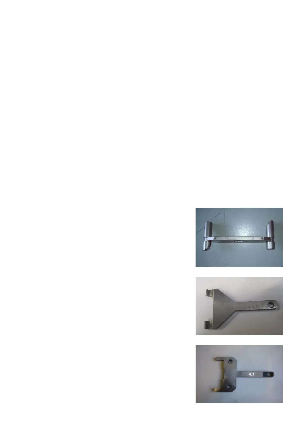
Fork tool 7.6 mm # EAM0122G95A for Front Transducer.
Use these tools on ALLOY vibratory system only to proper
adjust the fastening mean of the front transducer.
Fork tool 4.1mm # EAM0117G93A for Rear Transducer.
Use these tools on ALLOY vibratory system only to proper adjust
the fastening mean of the rear transducer.