32
TO ADJUST AND REPLACE THE SWITCH
Ø Lift the balancer from the ! oor.
Ø Remove the defective switch from the pedal.
Ø Remove the weight tray.
Ø Release the switches wires inside of the cabinet.
Ø Cut the wires of the defective switch and connect them to those ones of the new switch.
Ø Pull out the new wires through the cabinet
Ø Remove the wires of the defective switch from the connector X13
Ø Install the new switche wires to the connector X13.
Ø Fit l the new switch on the pedal bracket.
Ø Check the adjustment of the switch by pressing the pedal until end of stroke:
when the pedal is at the end of its stroke the micro switch must be engaged and still has to show some more
stroke.
Ø Unlock the 4mm set screw and adjust it until to have reached the correct adjustment.
Ø Fit the pedal assy to the balancer.
Ø Turn on the machine and check if the brake switche work " ne.
Ø Mount the pedal assy.
Ø Mount the weight tray.
4.18 CHECK AND REPLACEMENT OF DISTANCE POTENTIOMETER
" : Medium and big Phillips screwdriver, 13 and 14mm wrenches.
6 : 1.5h
i : Defective potentiometer may cause the following malfunctions:
1. Machine shows error with module 44.
2. Balancer show E92 turning it on.
TO CHECK THE POTENTIOMETER
Ø Check with service code C75, C80 and C92
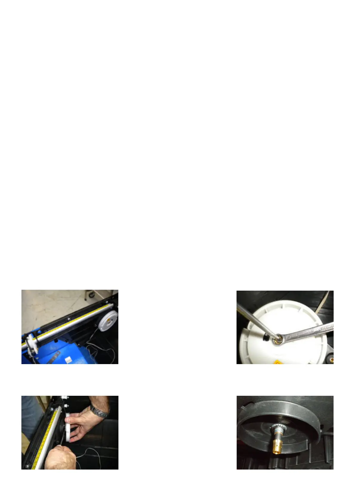
TO REPLACE THE POTENTIOMETER
Ø Disconnect the power from the rear of the machine.
Ø Remove the weight tray.
Ø Remove the 10mm nut holding the SAPE wheel to the frame.
Ø Remove the plastic wheel carefully in order to avoid the uncoil of the return spring.
Ø Remove the conical bushing.
Ø Remove the 13mm nut holding the potentiometer to the frame.