Engineering manual - SAB 193-233-283 S A-frame (including ATEX)
008831 en 2020.10
43/168
Technical description
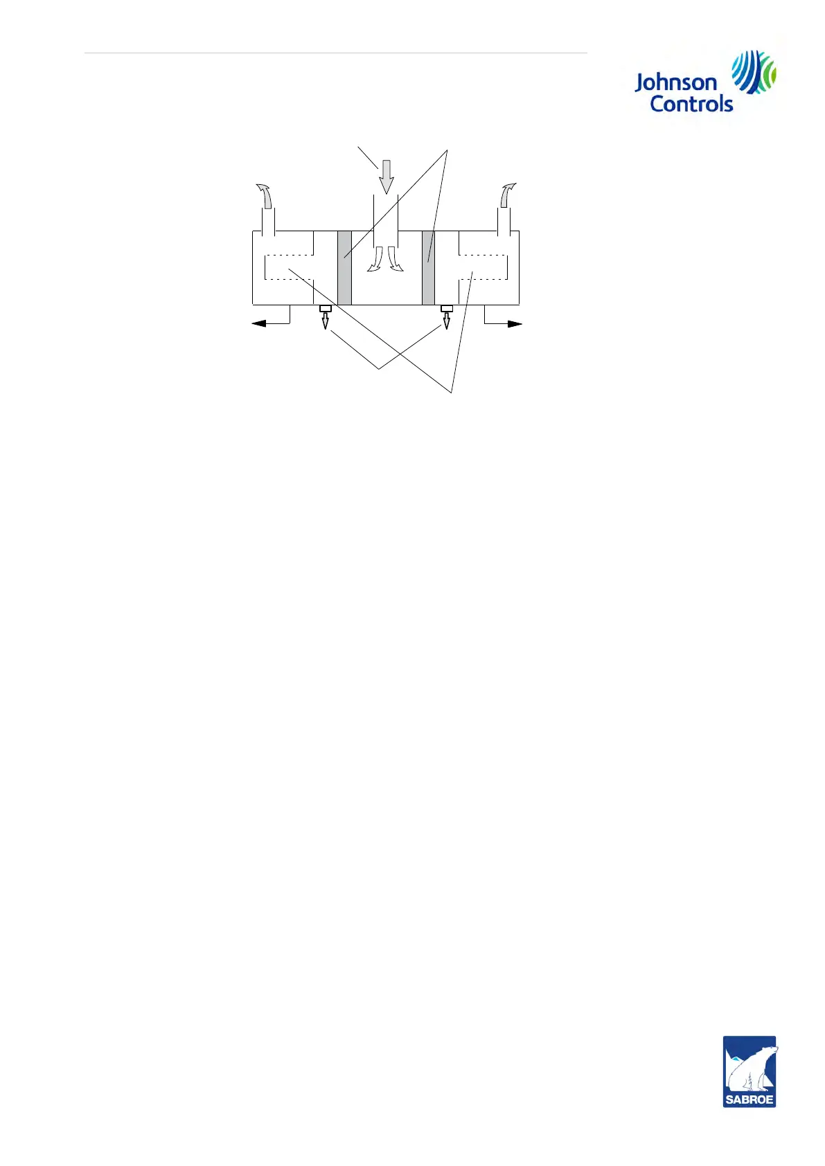
Fig. 21: OHU 04136
However, the discharge gas still contains a certain amount of fine oil drops, which are separated
as the discharge gas passes the fine oil separator elements (the fine filters). This oil is re-
turned to the compressor in separate piping systems as described later in this section.
Normally, the fine oil separator elements do not need to be inspected, but if it is considered neces-
sary, e.g. if increased oil consumption is observed in the unit, they can be removed through the
ends of the oil separator.
Oil return system for fine filter element
Whether the unit is delivered with one or two discharge lines, thus with one or two fine oil sepa-
rator elements, two oil return pipes will be fitted on the unit. See piping diagram.
The oil separator is fitted with an automatic oil return valve, see subsection 4.13
Oil vessel
As already mentioned, the lubricating oil is collected in the oil vessel. The oil level in the vessel
must always be visible in the sight glasses pos. 31. The correct amount of oil in the unit is stated
in Table 50, Table 51 and Table 52 in section 11.13 Oil charge.
The oil vessel contains one or two heating elements, pos. 30, which must always be switched on
when the unit is not operating and switched off when the compressor is started. Re-
member to switch off the heating elements when oil is drained off the oil vessel before an oil
renewal.
After a long period of standstill where the heating elements have been switched off they must be
connected for at least 8 hours before the unit is put into operation.
Demister
From the compressor
To oil vessel
Fine oil separator element, pos. 55
Oil return Oil return