Engineering manual - SAB 193-233-283 S A-frame (including ATEX)
42/168
008831 en 2020.10
Technical description
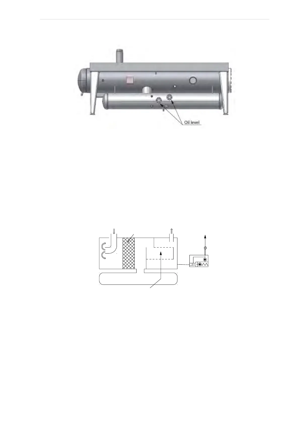
Fig. 19: Oil separator
Design and operating mode
As illustrated in Fig. 19 the oil separator system consists of two containers, an oil separator at the
top and an oil reservoir at the bottom. In the oil separator the oil is separated from the discharge
gas and taken to the oil reservoir. Both vessels are firmly connected to pipes which cannot be
separated.
Oil separator
As illustrated in Fig. 20 and Fig. 21 the discharge gas and the oil from the compressor first pass
the demisters where the main part of the oil is separated from the discharge gas and drained into
the oil vessel.
Fig. 20: OHU 04123
A
T245754_0
52
53
Fine separator element pos. 55
Vessel
Demister