INDOOR UNITS
3-6
TC-15001-rev.3
Models: (H,Y)IDH018B21S, (H,Y)IDH024B21S, (H,Y)IDH030B21S, (H,Y)IDH036B21S
and (H,Y)IDH048B21S
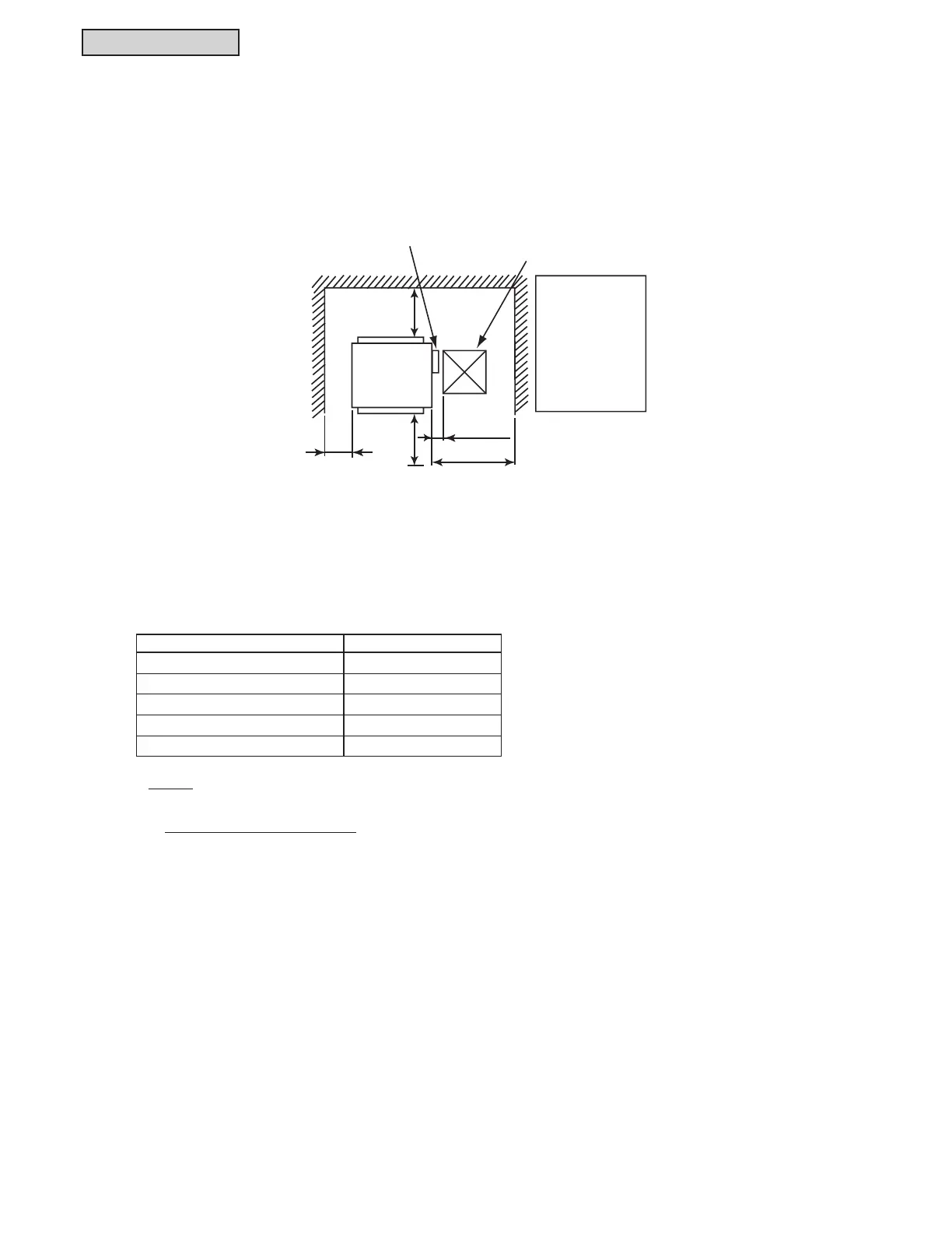
3.1.3.5 Operation Space
3.1.3.6 Sensible Heat Factor (SHF)
Model SHF*
(H,Y)IDH018B21S 0.83
(H,Y)IDH024B21S 0.85
(H,Y)IDH030B21S 0.83
(H,Y)IDH036B21S 0.83
(H,Y)IDH048B21S 0.84
Rear Side
≥ 39-3/8
(1000)
≥ 39-3/8
(1000)
View from Top
Front Side
(5-1/8(130))
≥ 23-5/8
(600)
≥ 23-5/8(600)
Electrical Box
(Unit: inch(mm))
Service Access
Door (≥
□
17-23/32(450))
If the ceiling board
cannot be found
for servicing,
prepare a service
access door
below the indoor
unit for removing
the indoor unit.
NOTE:
1. SHF is based on combinations within the VRF system and the following conditions:
Cooling Operation Conditions
Indoor Air Inlet Temperature: 80
o
F DB (26.7
o
C DB)
67
o
F WB (19.4
o
C WB)
Outdoor Air Inlet Temperature: 95
o
F DB (35.0
o
C DB)
Piping Length: 24 ft. 7-3/16 in. (7.5m)
Piping Lift: 0 ft .(0m)
 Loading...
