CONTROL SYSTEM
TC-15001-rev.3
6-29
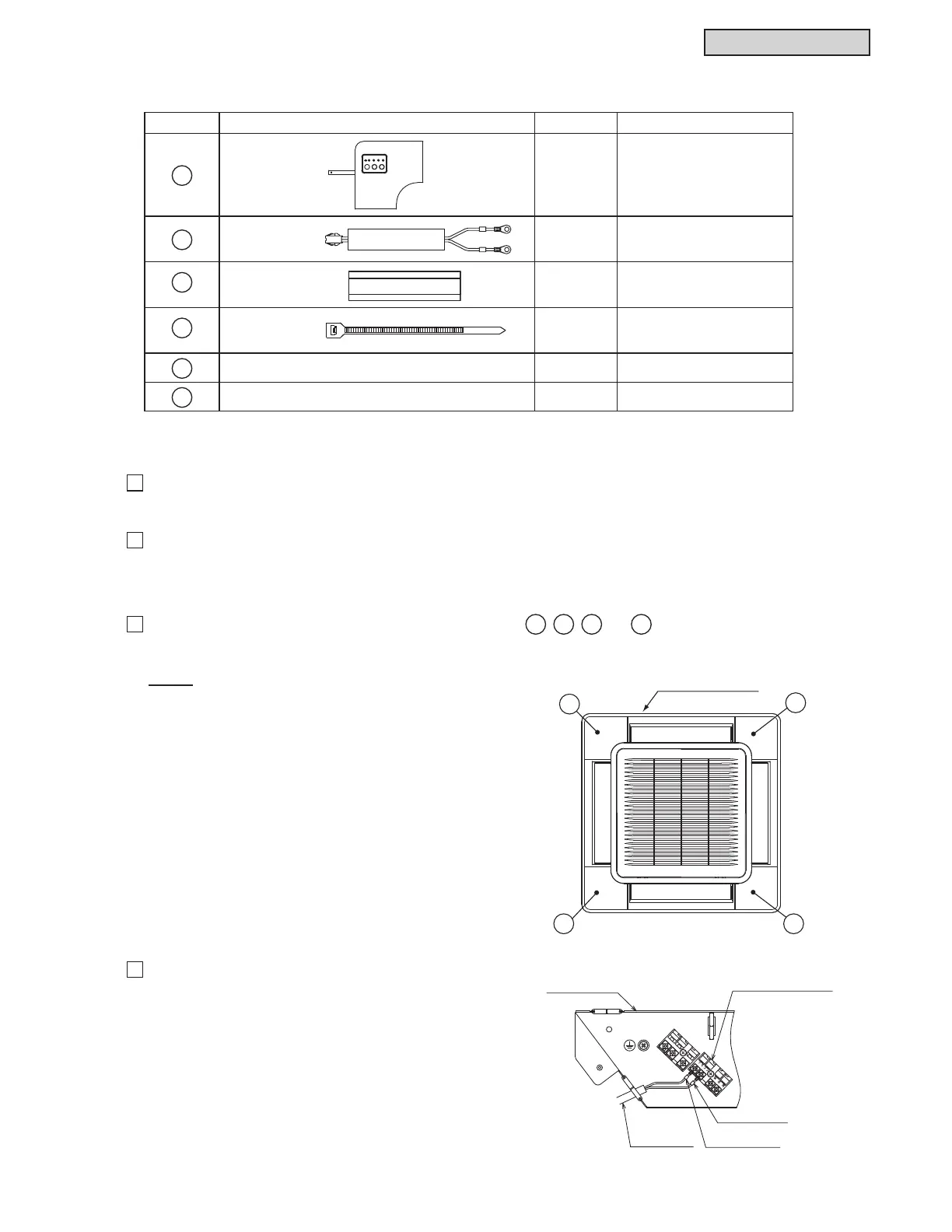
6.5.4 Accessories / Options
No. Accessory Qty 5HPDUNV
1
IR Receiver Kit
C4IRK01
1 With Connecting Cable
2
Connecting
Cable
1-
3
Wiring Cover 1
For Protection of
Connecting Cable
4
Plastic Band 3
For Securing Wiring Cover
and Connecting Cable
5
Installation Manual 1 -
6
Operation Manual 1 -
6.5.5 Installation
1
3HUIRUPWKHLQVWDOODWLRQZRUNIRUWKH,5UHFHLYHUNLWZKLOHWKHRSWLRQDOGHFRUDWLYHSDQHOLVEHLQJDWWDFKHGWR
the indoor unit.
2
:KHQWKH,5UHFHLYHUNLWLVDWWDFKHGDIWHUWKHGHFRUDWLYHSDQHOLVDWWDFKHGWRWKHLQGRRUXQLWWXUQ2))WKH
power source of the indoor unit, and remove the decorative panel. Removing the decorative panel should
be performed according to the Installation Manual for the decorative panel or the Service Manual.
3
7KLV,5UHFHLYHUNLWFDQEHDWWDFKHGWRDQ\RIIRXUFRUQHUVDQG
Determine the attachment location according to the purchaser’s request.
127(
7KH',3VZLWFKVHWWLQJIRUWKH,5UHFHLYHUNLWLV
possible at more than one function. If the optional
IXQFWLRQVHOHFWLRQLVUHTXLUHGSHUIRUPZRUN
DFFRUGLQJWRWKHVHFWLRQ³2SWLRQDO)XQFWLRQV´
EHIRUHWKH,5UHFHLYHUNLWLVDWWDFKHGWRWKH
decorative panel.
4
Connect the accessory connecting cable to the terminal
EORFN
Open the electrical box cover of the indoor unit. Attach
the connecting cable to terminals A and B in the electrical
box. (There is no polarity with terminals A and B.)
MP/
N
R/L1
S/L2
21
BA
B
A
Electrical Box
Terminal Block for
Controller
Mark Band “B”
Mark Band “A”
Connecting
Cable
Decorative Panel
1
2
34
 Loading...
