CONTROL SYSTEM
6-30
TC-15001-rev.3
6
Attach the decorative panel.
Refer to the Installation Manual for the decorative panel.
5
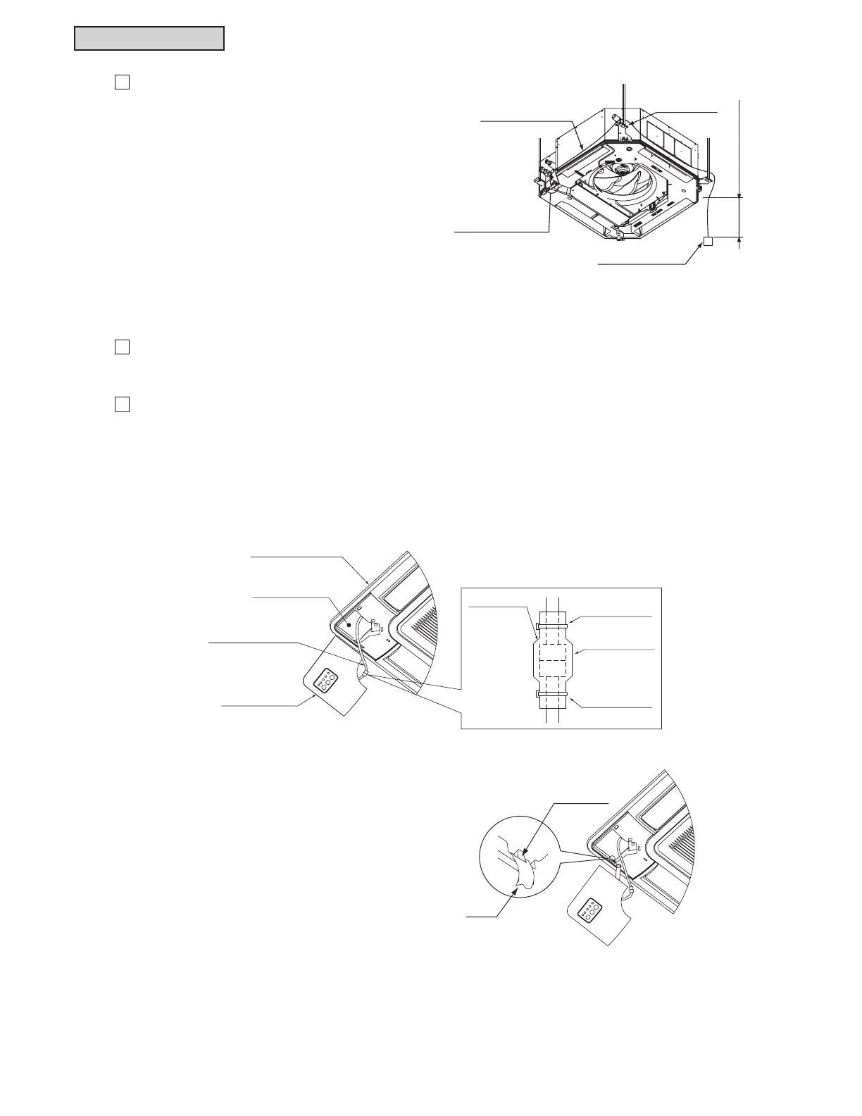
After attaching the connecting cable to each
WHUPLQDOWDNHLWRXWWRLQVLGHWKHIDOVHFHLOLQJRU
RXWVLGHRIWKHXQLW&RQQHFWLWWRWKH,5UHFHLYHUNLW
5HIHUWRWKH³,QVWDOODWLRQDQG0DLQWHQDQFH0DQXDO´
of the indoor unit for indoor unit wiring instruction.
When running the connecting cable, run it to the
LQVWDOODWLRQSRVLWLRQRIWKH,5UHFHLYHUNLWWKURXJK
WKHWRSRIWKH¿[LQJSODWHIRUWKHLQGRRUXQLW$IWHU
UXQQLQJWKHFRQQHFWLQJFDEOHWDNHWKHGLVWDQFHIURP
4 inches to 8 inches (from 101mm to 203mm) from
the indoor unit undersurface to the connecting cable
DVVKRZQLQWKH¿JXUHDWWKHULJKW
After running the connecting cable, clamp the extra
length of the connecting cable using the plastic band
and store it inside the ceiling.
7DNHWKHFRQQHFWLQJFDEOHRXWIURPWKHFRUQHUSRFNHWRIWKHGHFRUDWLYHSDQHO&RQQHFWWKHZLULQJIRU
WKH,5UHFHLYHUNLWWRWKHUHOD\FRQQHFWRUDVVKRZQEHORZ
After connecting, cover the relay connector connection with the wiring cover, and attach the wiring
cover with the plastic bands.
$I¿[WKHEDQGDWWKHUHDUVLGHRIWKH,5UHFHLYHU
NLWRQWRWKHSURMHFWLRQDWWKHGHFRUDWLYHSDQHO
DVVKRZQLQWKH¿JXUHDWWKHULJKW
7
$IWHUWKHLQVWDOODWLRQZRUNIRUWKHGHFRUDWLYHSDQHOLVFRPSOHWHGDWWDFKWKH,5UHFHLYHUNLW
Projection
Band
Connecting Cable
Fixing Plate
Relay Connector
Indoor Unit
Wiring Connection
4~8inch
(101~203mm)
Decorative Panel
Corner Pocket
Connecting Cable
Plastic Band
Relay
Wiring Cover
Plastic Band
Connector
IR Receiver Kit