CONTROL SYSTEM
6-60
TC-15001-rev.3
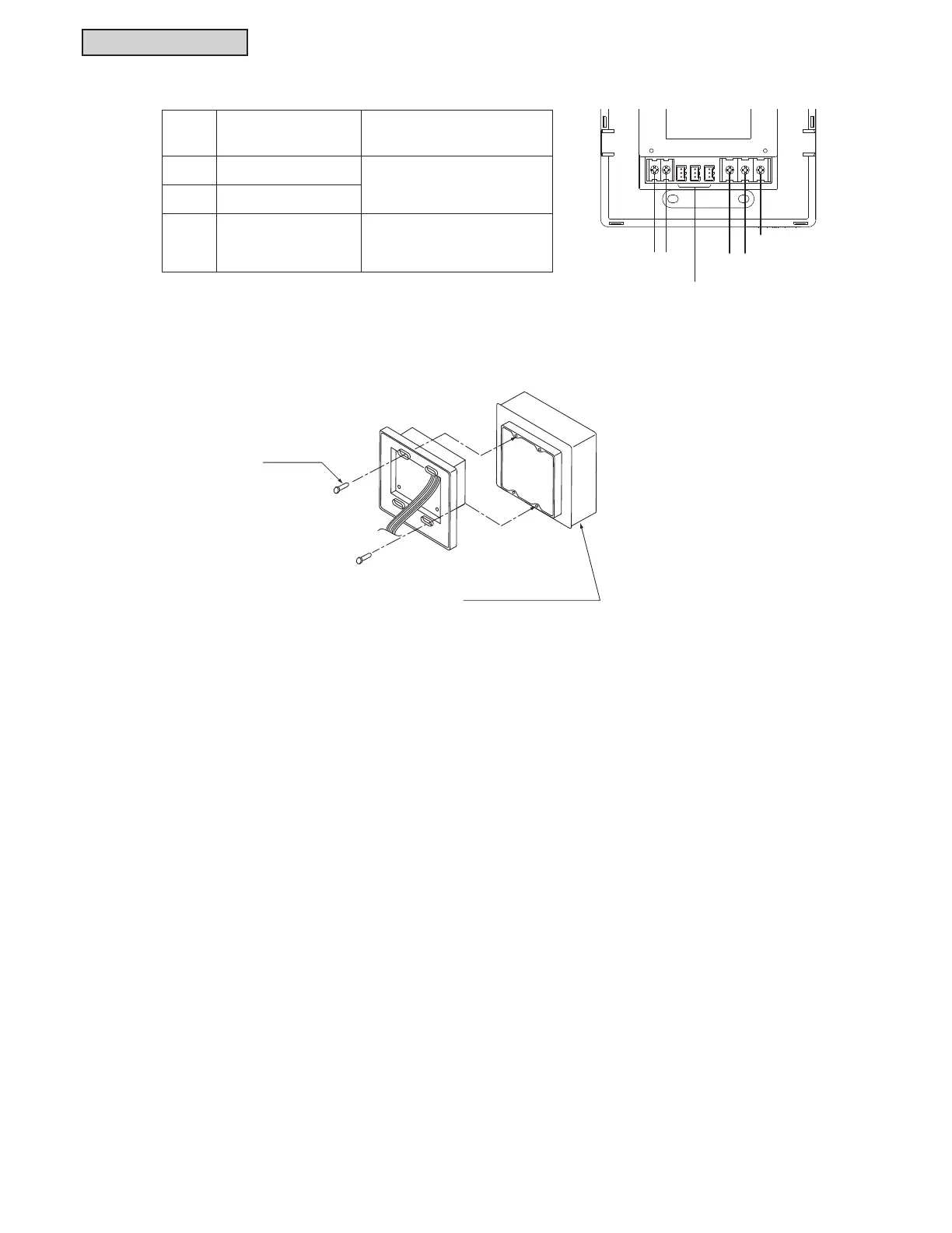
3) Connect the wiring to the terminal board of the mini central controller.
4) Attach the steel box (
option
) with the accessory mounting screw (M4 x 5/8 inch).
Terminal
Board
Use Connection Procedure
TB1 For Power Supply
M3 Screw-on terminal
Round Terminal Connection
Tightening Torque 0.4 ft·lbs
TB2
For H-LINK Communication
CN1 ~ 3 )RU([WHUQDO,QSXW2XWSXW
Connector, three pin
Insert connector cords (accessory)
XQWLOKHDULQJFOLFNLQJVRXQG
M4 Screws
(Q’ty 4)
Steel Box (Option)
H-LINK
(Non-pole)
24VAC
Terminals for External Input/Output
Refer to item 6.8.14.
FG
 Loading...
