Engineering manual - SAB 355 Screw compressor unit (including ATEX)
50/156
004100 en 2020.10
Technical description
Note: To slow all valve movements - loading, unloading and Vi change - throttle valve 2.
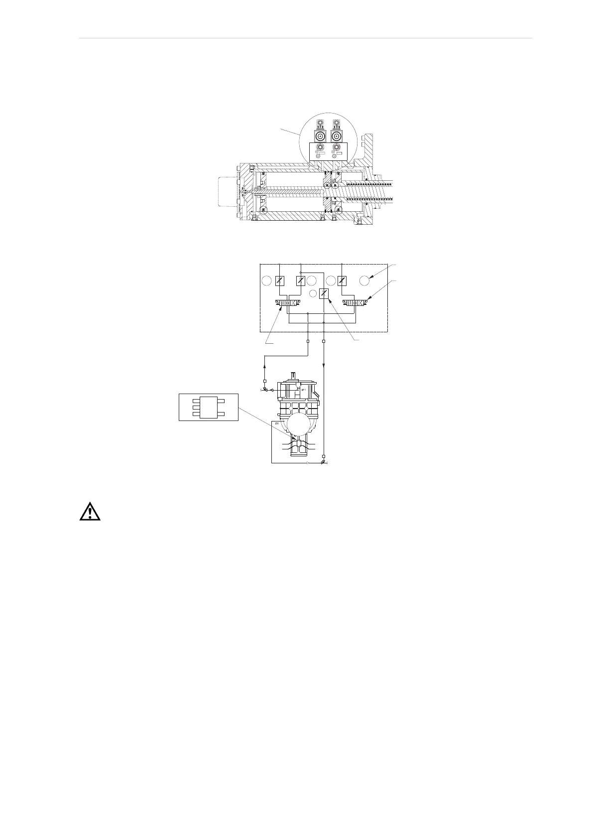
Fig. 26: Volumizer volume ratio control
Fig. 27: Compressor hydraulic system
Caution!
Never open valve BP and valve SC2 at the same time during compressor operation.
See Fig. 27 for port references.
• Open the valve at SC3
• SC4 not used
Compressor V
i
increase. The volume ratio V
i
is increased when the MSS solenoid valve, YY3, is
energised, and oil flows from the oil manifold through the valve ports, P and A, to the compressor
port, SC3, enters the increase side of the cylinder and overcomes the decrease spring tension.
The inboard side of the slide stop piston is at suction pressure.
Compressor V
i
decrease. The volume ratio V
i
is decreased when the MSS solenoid valve, YY4,
is energised, which permits oil to vent from port A to T with assistance from the unloader spring
via port SC3.
To control the rate of the V
i
change, throttle the needle valve at the SC3 port.
4.1.16 Compressor oil cooling systems
The unit can be equipped with one of several systems for controlling the compressor oil tempera-
ture. They are single or dual-port liquid injection and refrigerant-cooled (thermosyphon) or
water-cooled oil coolers. Each system is automatically controlled, independent of compressor
loading or unloading.
SC1
SC3
S
ee hydraulic
schematic for
functional
view of valve
operation
COMPRESSOR TOP VIEW
HYDRAULIC SCHEMATIC
SIZES 496, 676, 856, 1080
YY4 (DECREASE VI)
YY2 (LOAD)
(INCREASE VI) YY3
(UNLOAD) YY1
Valve 2
SCREW IN FLOW
REGUL
ATING
NEEDLE VALVE
DIRECTION
C
ONTROL VALVE
SC4 NOT USED
SC3 SC2
SC1
SC1
SC2
SC3
SC4
YY1YY2
YY3YY4
BP
sv-3
sv-2
DIRECTION
C
ONTROL
VALVE
P
T
Valve 1
SC4
BP
SC2
SC3
SC1
A
B
P
T
T
P
B
A
1
1
2
2
1
2
1
2