Engineering manual - SAB 355 Screw compressor unit (including ATEX)
004100 en 2020.10
85/156
Technical data
6.4 Planning the machine room
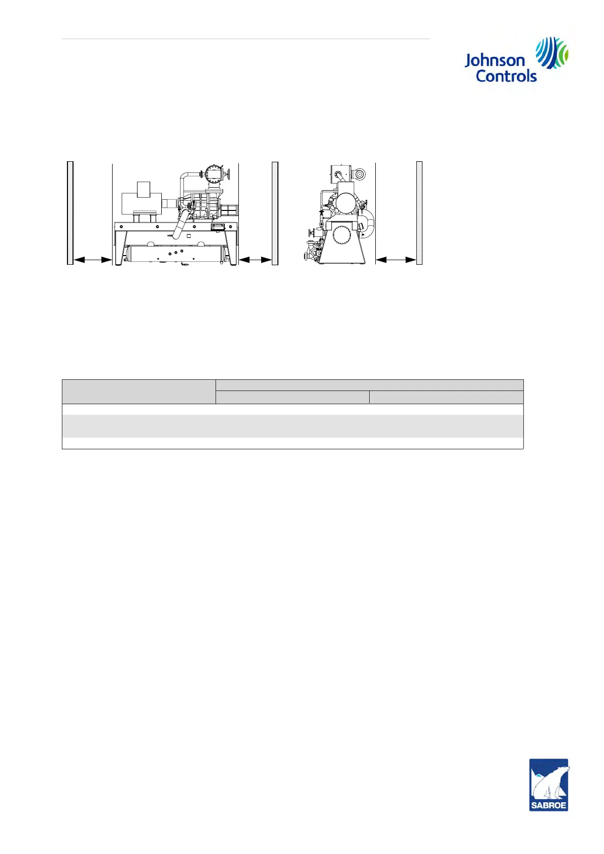
When planning the machine room, make sure that there is enough space around the plant to
make easy access for repair and maintenance tasks. Fig. 61 shows the minimum spacing in
millimetre.
Fig. 61: Planning the machine room
6.5 Minimum compressor flow at 3550 rpm
The minimum flow capacity for each compressor varies depending on its geometry and its operat-
ing conditions. Typical minimum flow for each of the compressor models is listed below. Table 15
represents minimum suction flow with the slide valve fully unloaded.
Unit
Minimum flow*
CFM
m
3
/h
SAB 355 S 351 596
SAB 355 L
477
810
SAB 355 E 912 1550
SAB 355 X 1662 2824
Table 15: Minimum suction flow
* at 3550 rpm
6.6 Operating limits
The diagram below, Fig. 62, shows the permissible working range for the compressor. Always con-
tact your local Johnson Controls representative before letting the compressor operate under op-
erating conditions outside the specified working range.