Engineering manual - SAB 355 Screw compressor unit (including ATEX)
64/156
004100 en 2020.10
Technical description
2. A refrigerant-side safety valve is required in this location only when refrigerant isolation valves
are installed between the cooler and thermosyphon receiver. If no valves are used between the
cooler and TSOC receiver, the safety valve on the TSOC receiver must be sized to handle the vol-
ume of both vessels. Then, the safety valve on the cooler vent (liquid refrigerant side) can be
eliminated.
3. The system receiver must be below the thermosyphon receiver in this arrangement.
4.1.30 Water-cooled oil cooling
The plate and shell or plate-and-shell type water-cooled oil cooler is mounted on the unit com-
plete with all oil piping. The customer must supply adequate water connections. Determine the
size of the water-cooled oil cooler supplied with the unit as outlined in COMP1. The water supply
must be sufficient to meet the required flow.
Johnson Controls Denmark recommends a closed-loop system for the waterside of the oil cooler.
Careful attention to water treatment is essential to ensure adequate life of the cooler if cooling
tower water is used. It is imperative that the condition of cooling water and closed-loop
fluids are analyzed regularly and as necessary and maintained at a pH of 7.4, but not
less than 6.0 for proper heat exchanger life. After initial start-up of the compressor package,
the strainer at the inlet of the oil cooler should be cleaned several times in the first 24 hours of
operation.
In some applications, the plate and shell oil cooler may be subjected to severe water conditions,
including high temperature and/or hard water conditions. This causes accelerated scaling rates
which will penalise the performance of the heat exchanger. A chemical cleaning process will ex-
tend the life of the plate and shell heat exchanger. It is important to establish regular cleaning
schedules.
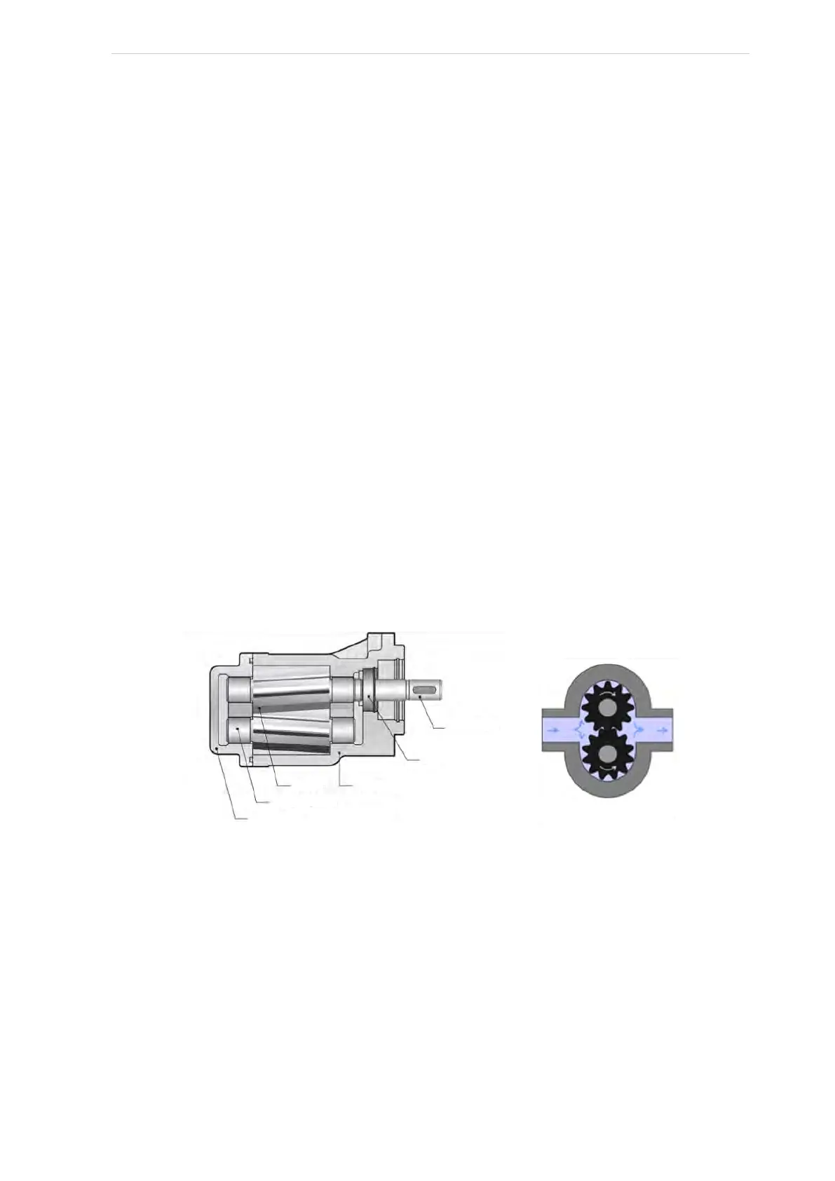
4.1.31 KRACHT oil pump
Fig. 40
The oil pump is an external toothed gear pump, which works according to the positive displace-
ment principle. The pump is equipped with a mechanical seal, cooled and vented through inter-
nally bored channels.
The pump has an integrated by-pass valve – a pressure relief valve with a factory setting of 3.5
bar, see Fig. 41. It is possible to adjust the valve from 0 to 15 bar by removing the hexagon nut,
then setting the response pressure using the adjusting screw and then securing the adjusting
screw with the hexagon nut.
Drive shaft end
Shaft seal
Housing Gear unit
Plain bearing bushes
End cover
External gear pump