Engineering manual - SAB 355 Screw compressor unit (including ATEX)
004100 en 2020.10
63/156
Technical description
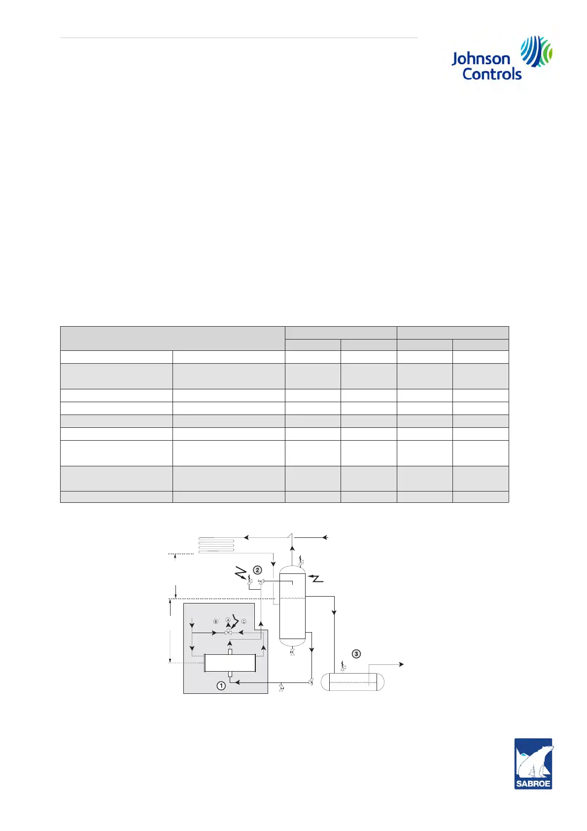
The principle of operation is as follows, see Fig. 39. A supply of high pressure liquid is maintained
in a receiver at a predetermined minimum head above the oil cooler and below the condenser.
Gravity causes the liquid refrigerant to flow to the oil cooler where a portion of the liquid is boiled
off, thereby cooling the hot oil. New liquid from the receiver displaces the lighter refrigerant
liquid/vapour mixture which rises to the receiver, dropping out the remaining liquid before allow-
ing the vapour to return to the condenser, completing the cycle.
Piping arrangement for thermosyphon oil cooling systems
The components and piping of a thermosyphon oil cooling system include a liquid source at con-
densing pressure, adequate static heads to provide fluid flow, appropriate control valves, safety
relief valves, service valves and pump-out connections. The arrangement of component place-
ment and fluid flow requirements must be designed to suit the individual refrigeration system lay-
out with consideration given to piping safety practices.
The component and piping arrangement in Fig. 39 is intended only to illustrate the operating prin-
ciples of thermosyphon oil cooling. Other component layouts may be better suited for a specific
installation. For additional information on thermosyphon oil cooling, please refer to Frick publica-
tion 070.900-E.
Unit
Type of cooler Connection
Dia. Plates Inlet Outlet
SAB 193 S, L
High-stage
14 in. 116 3 in. 3 in.
SAB 193 S, L and SAB
233 S, L, E
Booster 14 in. 66 2 in. 2 in.
SAB 233 S, L
High-stage
14 in. 190 3 in. 3 in.
SAB 233 E
High-stage
14 in. 288 3 in. 4 in.
SAB 283 S, L
Booster 24 in. 56 3 in. 3 in.
SAB 283 S, L
High-stage
24 in. 136 4 in. 5 in.
SAB 283 E, X and SAB
355 S, L
High-stage 24 in. 188 4 in. 5 in.
SAB 283 E, X and SAB
355 S, L, E
Booster 24 in. 72 3 in. 3 in.
SAB 355 X
Booster
24 in. 136 4 in. 5 in.
Table 7: Oil cooler data
Fig. 39
1. The thermosyphon oil cooler is supplied with the oil side piped to the compressor unit and stub
ends supplied on the refrigerant side.
System condenser
Vapour
Safety
v
alve
Static head
t
o overcome
condenser
pressure drop
Thermosyphon
r
eceiver
Liquid overflow
dr
ain to receiver
To system
e
vaporator
System
receiver
(Mounted below
thermosyphon r
eceiver level)
Liquid
le
vel
Oil temp.
c
ontrol valve
Hot
Cool
Cool
oil out
Refrigerant in
Refrigerant
Hot oil in
Plate cooler
T
SOC
6 ft.
(183 cm)
M
in.
out