Engineering manual - SAB 355 Screw compressor unit (including ATEX)
66/156
004100 en 2020.10
Technical description
Standard lubrication system limits, high-stage
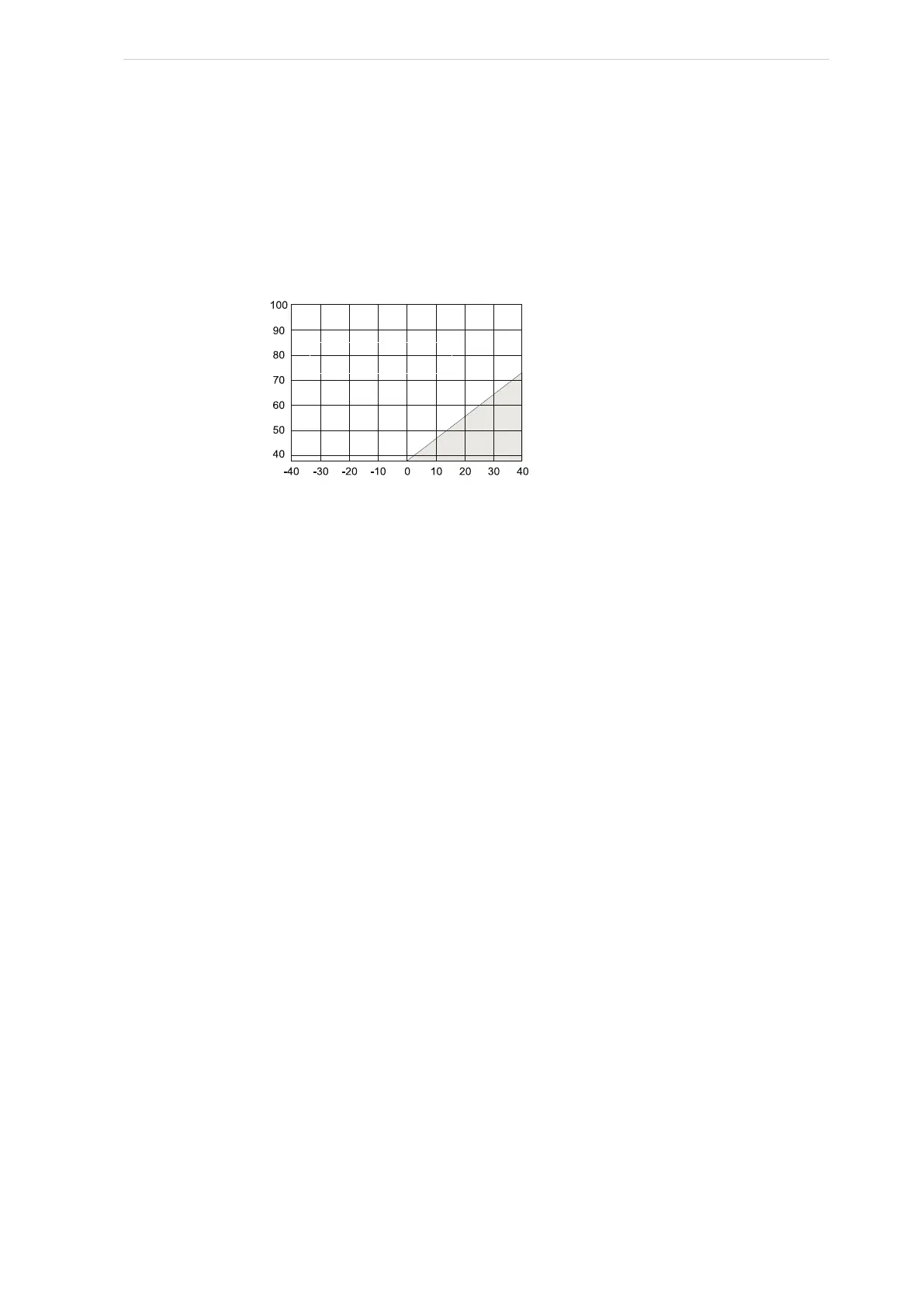
The standard system for compressor operation without a lubricating oil pump may be used on
high-stage applications shown in the clear area of Fig. 44. The optional demand oil pump is re-
quired only on low differential pressure applications shown in the shaded area in Fig. 44. Where
the condensing temperatures fluctuate into the shaded area only occasionally during the winter,
the demand pump avoids unnecessary consumption of pump horsepower.
Fig. 44: Standard lubrication system limits, high-stage
Start-up
The pump must only run without an oil flow for brief periods of time because of the bearings and
shaft seal.
Service
The oil pump is designed as one unit and should therefore not be disassembled.
4.1.32 Economiser, high-stage (optional)
The economiser option provides an increase in system capacity and efficiency by subcooling liquid
from the condenser through a heat exchanger or flash tank before it goes to the evaporator. The
subcooling is provided by flashing liquid in the economiser cooler to an intermediate pressure
level. The intermediate pressure is provided by a port located part way down the compression
process on the screw compressor. As the screw compressor unloads, the economiser port will
drop in pressure level, eventually being fully open to suction. Because of this, an output from the
microprocessor is generally used to turn off the supply of flashing liquid on a shell and coil or DX
economiser when the capacity falls below approximately 45%-60% capacity (85%-90% slide
valve position). This is done because the compressor will be more efficient operating at a higher
slide valve position with the economiser turned off, than it will at a low slide valve position with
the economiser turned on. Please note, however, that shell and coil and DX economisers can be
used at low compressor capacities in cases where efficiency is not as important as assuring that
the liquid supply is subcooled. In such cases, the economiser liquid solenoid can be left open
whenever the compressor is running.
Due to the tendency of the port pressure to fall with decreasing compressor capacity, a back-pres-
sure regulator valve (BPR) is generally required on a flash economiser system (Fig. 50) in order to
maintain some preset pressure difference between the subcooled liquid in the flash vessel and
the evaporators. If the back-pressure regulator valve is not used on a flash economiser, it is possi-
ble that no pressure difference will exist to drive liquid from the flash vessel to the evaporators,
since the flash vessel pressure will approach suction pressure at a decreased slide valve position.
In cases where wide swings in pressure are anticipated in the flash economiser vessel, it may be
necessary to add an outlet pressure regulator to the flash vessel outlet to avoid overpressure of
°F
-40-34.4-28.9-23.3-17.8
-12.2
-6.7-1.14.4
°C
°F
4.4
10
15.6
21.1
26.7
32.2
37.8
°C
Pressure differential is acceptable for
standar
d system operation in the
clear area. A demand oil pump
option is required for operation in
the shaded area.
Saturated suction temperature
Condensing temperature