JOHNSON CONTROLS
118
FORM 160.54-O1
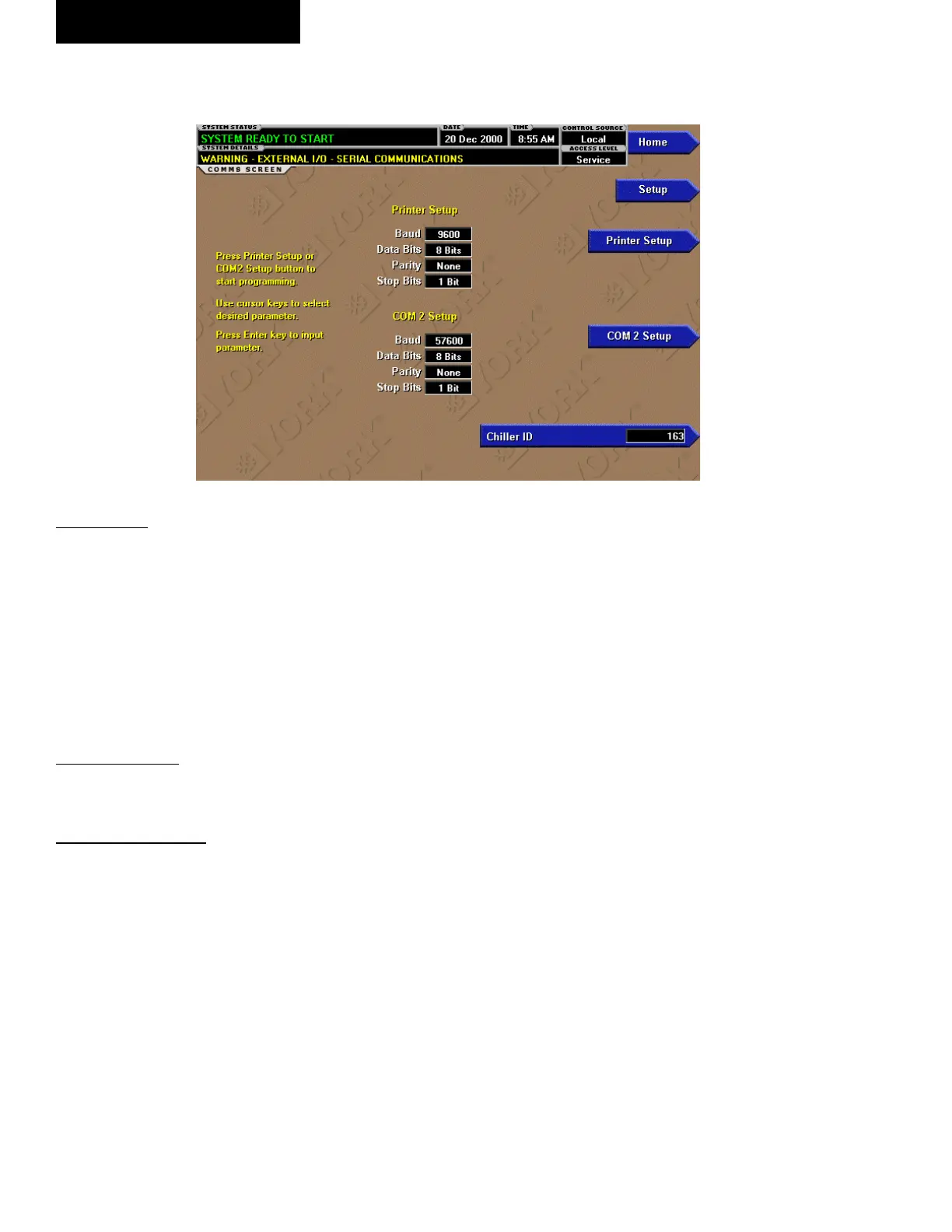
COMMS SCREEN
OVERVIEW
(Screen shown from all applications equipped with Flash
Memory Card version C.MLM.01.05.xxx and later.
Screen layout from earlier versions slightly different.)
This screen allows denition of the necessary com-
munications parameters. Refer to PRINTER Section
of this book for details of the Printer connections and
setup. Presently, there are no COM 2 communications
features available.
DISPLAY ONLY
None
PROGRAMMABLE
Chiller ID
Access Level Required: OPERATOR
Dene the numeric chiller ID when used within an ISN
network of chillers. This ID number is also printed at
the top of reports obtained with a local printer.
Printer Setup and COM 2 Setup
Access Level Required: OPERATOR
Pressing either key places a green selection box around
the rst changeable parameter. Use the ▲ and ▼ keys
to place the selection box around the desired parameter
to be changed. With the selection box around the desired
parameter, press the ENTER ‘’ key. A dialog box is
displayed permitting data entry. In VSD or LCSSS Mod-
bus Protocol conguration, COM2 button is not shown
because COM2 serial port is used for this interface.
Printer Baud Rate
Dene the baud rate at which the panel shall commu-
nicate to the printer.
Printer Data Bit(s)
Dene the number of data bits with which the panel shall
communicate to the printer.
Printer Parity Bit(s)
Dene the number of parity bits with which the panel
shall communicate to the printer.
Printer Stop Bit(s)
Dene the number of stop bits with which the panel shall
communicate to the printer.
COM 2 Baud Rate
Dene the baud rate at which the panel shall commu-
nicate through the modem port.
COM 2 Data Bit(s)
Dene the number of data bits with which the panel shall
communicate to the modem port.
COM 2 Parity Bit(s)
Dene the number of parity bits with which the panel
shall communicate through the modem port.
COM 2 Stop Bit(s)
Dene the number of stop bits with which the panel shall
communicate through the modem port.
00470VIP
FIG. 30
OptiView Control Center
 Loading...


