FORM 160.54-O1
13
JOHNSON CONTROLS
When in this position, the chiller will not run under
any condition. For safety reasons, this position is
required for many maintenance tasks to be completed
(such as proximity probe and vane calibration). In
addition, the switch must be placed in this state
following a Safety shutdown before the chiller is
allowed to restart. This guarantees that manual inter-
vention has taken place and the shutdown has been
acknowledged.
The switch can only remain in this position when
being acted upon by a manual force. Once the user
has released the switch, it automatically reverts to
the RUN position. Generally, this state only occurs
momentarily as the operator attempts to locally start
the unit. Once this position has been sensed, if all
fault conditions are cleared, the unit will enter the
system prelube (start sequence).
When in this position, the chiller is able to operate.
The switch spring-returns to this state after it has
been toggled to the START position. When in this
state, the chiller is allowed to function normally, and
will also allow the chiller to automatically restart fol-
lowing a Cycling shutdown. The switch must be in
this state to receive a valid remote start signal when
operating under a remote control source.
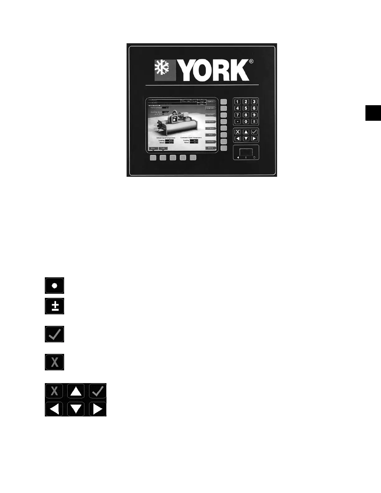
OPTIVIEW CONTROL CENTER
The OptiView™ Control Center display is highlighted
by a full screen graphics display. This display is nested
within a standard keypad, and is surrounded by “soft”
keys which are redened based on the currently dis-
played screen. Eight buttons are available on the right
side of the panel, and are primarily used for navigation
between the system screens. At the base of the display
are 5 additional buttons. The area to the right of the key-
pad is used for data entry with a standard numeric keypad
provided for entry of system setpoints and limits.
The Decimal key provides accurate entry of
setpoint values.
A +/- key has also been provided to allow entry
of negative values and AM/PM selection during
time entry.
In order to accept changes made to the chiller
setpoints, the Check key is provided as a univer-
sal ‘Enter’ key or ‘Accept’’ symbol.
In order to reject entry of a setpoint or dismiss
an entry form, the ‘X’ key is provided as a uni-
versal ‘Cancel’ symbol.
Cursor Arrow keys are pro-
vided to allow movement on
screens which contain a large
amount of entry data. In ad-
dition, these keys can be used
to scroll through history and
event logs.
The Start/Stop control is operated via a three-position
rocker switch. When toggled all the way to the right, it is
considered in the STOP/RESET position. When in the
middle position, this is considered the RUN state. When
toggled to the left-most position, it is considered in the
START state. Each state is described in detail below:
• STOP / RESET (O)
• START (◄ )
• RUN (
▀
)
29348A
FIG. 3
2