JOHNSON CONTROLS
44
FORM 160.54-O1
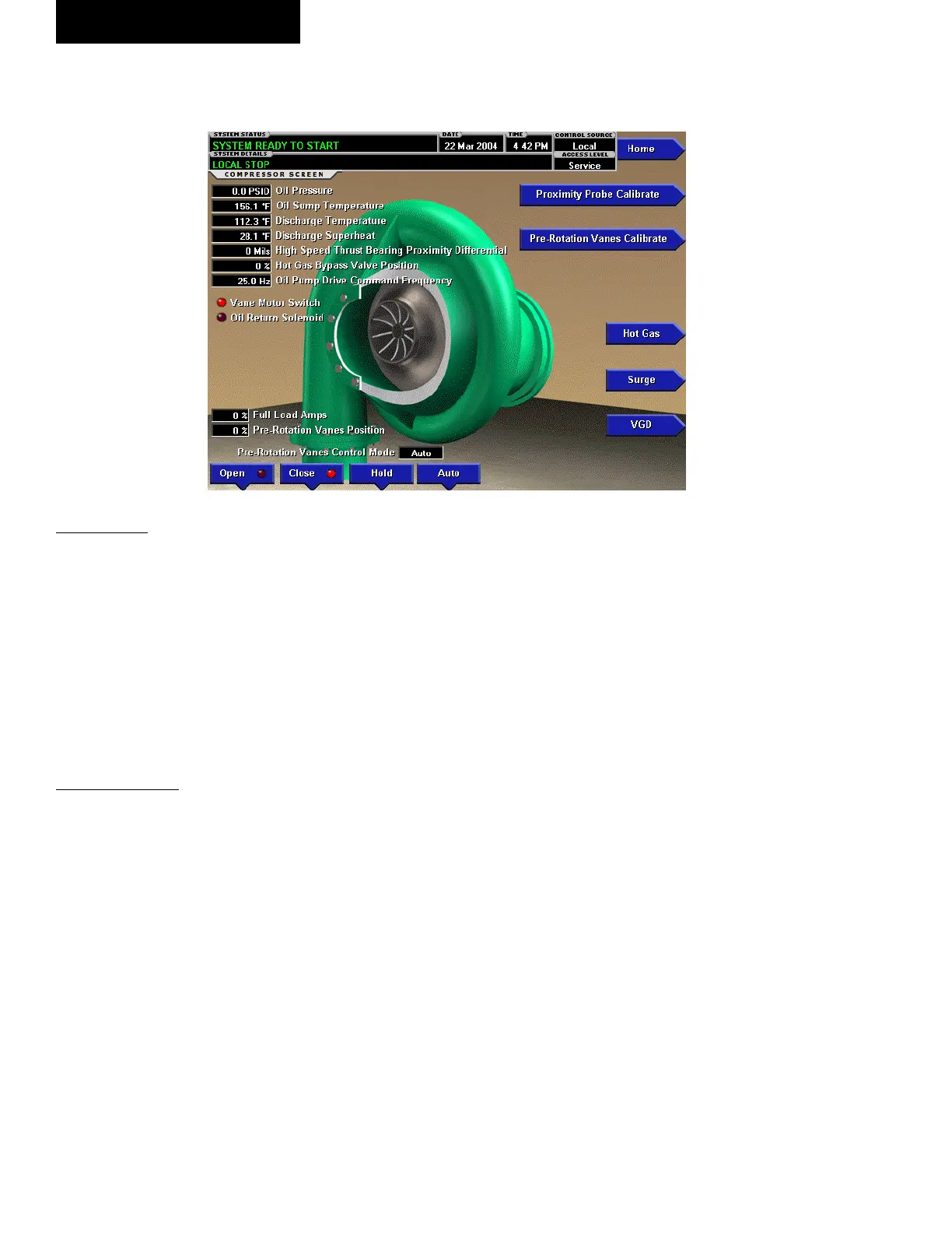
COMPRESSOR SCREEN
(STYLE E AND EARLIER CHILLERS WITH G, H, OR J COMPRESSORS
AND STYLE G CHILLERS WITH K COMPRESSORS)
OVERVIEW
This screen displays a cutaway view of the chiller
compressor, revealing the impeller, and shows all condi-
tions associated with the compressor. In addition, with
the proper Access Level, the pre-rotation vanes may
be manually controlled. Animation of the compressor
impeller indicates whether the chiller is presently in a
RUN condition. This screen also serves as a gateway
to sub-screens for calibrating the pre-rotation vanes,
calibrating the proximity probe, conguring the Hot Gas
Bypass, or providing advanced control of the compressor
motor Variable Speed Drive.
DISPLAY ONLY
Oil Pressure
Displays the pressure differential between the high side
oil pressure transducer (compressor bearing input) and
the low side oil pressure transducer (oil sump). The
displayed value includes offset pressure derived from
auto-zeroing during the system prelube. If either of the
transducers used to calculate this differential is out of
range, the display eld will show XX.X.
The offset pressure is the pressure differential between
the high oil pressure (HOP) transducer and the low oil
pressure (LOP) transducer outputs during a three (3)
second period beginning ten (10) seconds into the system
prelube. During this time, the transducers will be sens-
ing the same pressure and their outputs should indicate
the same pressure. However, due to accuracy tolerances
in transducer design, differences can exist. Therefore
to compensate for differences between transducers and
assure differential pressure sensing accuracy, the offset
pressure is subtracted algebraically from the differential
pressure. The offset pressure calculation will not be
performed if either transducer is out of range. The offset
value will be taken as 0 PSI in this instance.
Oil Sump Temperature
Displays the temperature of the oil in the sump
Discharge Temperature
Displays the temperature of the refrigerant in its gaseous
state at discharge of the compressor as it travels to the
condenser.
Discharge Superheat
(Flash memory card version C.MLM.01.02 or later)
Displays the Discharge superheat, calculated as (Discharge
Temperature – Condenser Saturation temperature).
High Speed Thrust Bearing
Oil Drain Temperature
Displays the temperature of the oil in the high-speed thrust
bearing drain line. Not applicable to chillers equipped
with Flash Memory Card version C.MLM.01.03 and
higher.
High Speed Thrust Bearing
Proximity Differential
Displays the distance between the high-speed thrust col-
lar and the tip of the proximity probe. This measurement
takes into account the reference position established at
the time of compressor manufacture.
High Speed Thrust Solenoid
(LED - Style E-R22 Only)
Indicates whether the solenoid is presently energized.
Vane Motor Switch (LED)
Indicates whether the vanes are completely closed.
LD09574
FIG. 9A
OptiView Control Center