All Copyright and rights are the property of Johnston Sweepers Ltd
V Range 501 l 651 l 801 Maintenance Manual
MA1:10
Chapter - Scheduled Maintenance
Throttle Settings
These engines have their own ECU and the speeds are preset and can only be checked. (Except for
Dieselmax Stage 3a).
1 Raise the body.
2 With the fan safety flap closed and a plate (suitably secured with clamps) completely blanking the fan inlet.
3 Start the engine and allow to warm up.
4 Check the tickover speed and the maximum flight speeds. If these are incorrect, they must be reset
by an authorised distributor.
5 NOTE : Stop the engine before removing the fan inlet blanking plate and lowering the body.
ENGINE
TYPE
JOHNSTON
PART NO.
IDLE SPEED
Rev./Min.
(Max Off Load)
Rev./Min.
JCB Ecomax 444
Standard Power Engine 24V (55kW - S3b)
7017176 850 2000
JCB Ecomax 444
Standard Power Engine 12V (55kW - S3b)
7028433 850 2000
JCB Ecomax 444
High Power Engine 24V (93kW - S3b)
7017181 850 2000
JCB Ecomax 444
High Power Engine 12V (93kW - S3b)
7025710 850 2000
John Deere 4045HF285
High Power Engine 12V only (86kW - Tier 3)
283791-12 850 2000
JCB Dieselmax 444
Standard Power Engine 24V (85kW - S3a)
7028407 900 2200
JCB Ecomax 444
High Power Engine 24V (93kW - Tier 4)
7039194 850 2000
JCB Ecomax 444
High Power Engine 12V (93kW - Tier 4)
7039193 850 2000
AUXILIARY ENGINE
Page Issue B
VT - Twin Engine
M02MA-058
A
B
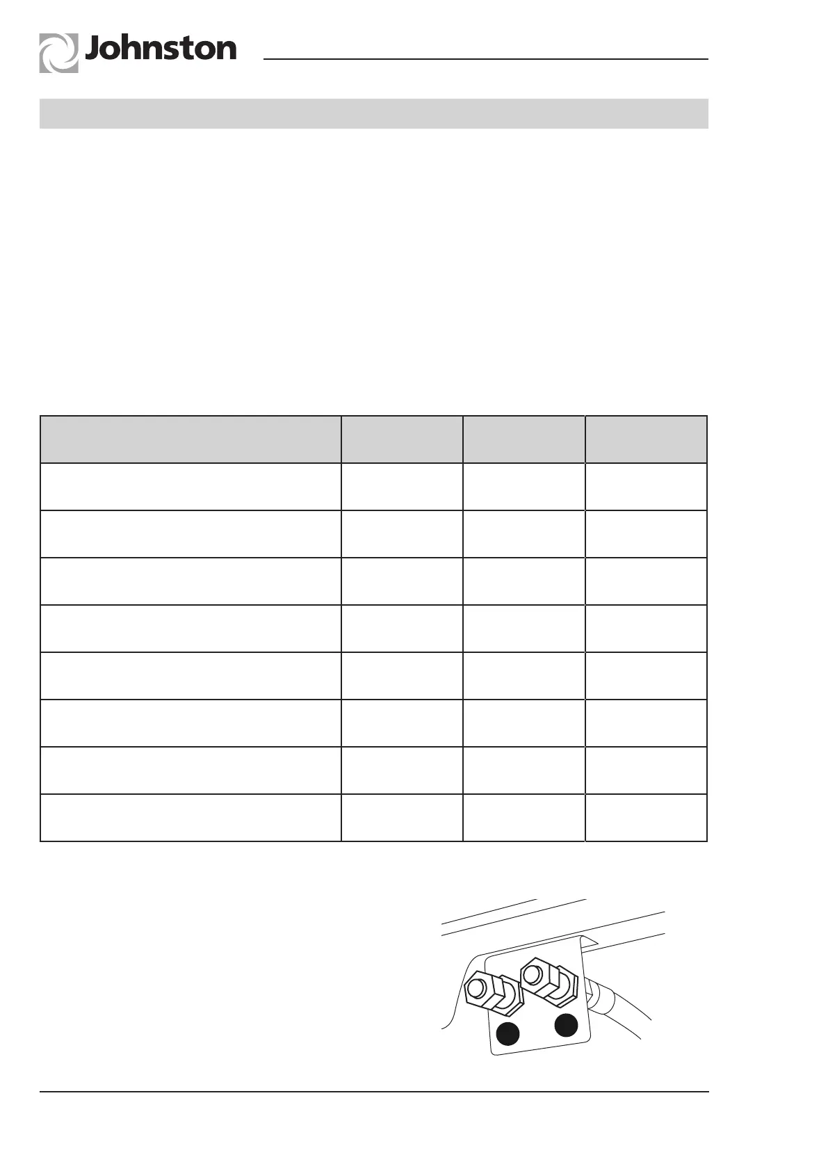
Auxiliary Engine and Gearbox Drain Plugs
The drain plugs for the auxiliary engine (B) and gearbox
(A) are located on a bracket near to the Powapack access
ladder.