function
The XP8
10
3 of
fers six (6) programmable mixes to be used for a
number of dif
ferent purposes. The functions allows mixing any
one channel to any other channel.
The mix can remain ON at all times, or be switched OFF in
flight using a number of dif
ferent switches. Refer to Figure 4
.13
B
and 4
.1
3C. Each channel is identified by a four character name
(i.e., Aileron - AILE, Elevator - ELEV
, etc.). The channel appearing
first is known as the “master channel,” or the channel to which
you want to mix. The second channel is known as the “slave
channel,” or the channel that is being mixed into the master
channel. For example, AILE - RUDD would indicate aileron to
rudder mixing — each time the aileron stick is moved, the
aileron will deflect, and the rudder will automatically move in the
direction and to the value input. Mixing is propor
tional, so
small inputs of the master channel will produce small outputs of
the slave channel. Each programmable mix has a mixing
“of
fset.” The purpose of the mixing of
fset is to redefine the
neutral position of the slave channel.
Multi-Point Programmable Mixing
Programmable mixes 1 and 2 have the capability for multi-point
programmable mixing. The graphic mixing curve, located on the
right side of your screen, indicates the mixing cur
ve selected
and is a useful reference tool when adjusting or storing points.
Up to 5 points can be stored, and these points can be moved
independently to any desired ser
vo position from 0 to 100%.
(Refer to figure 4
.
1C).
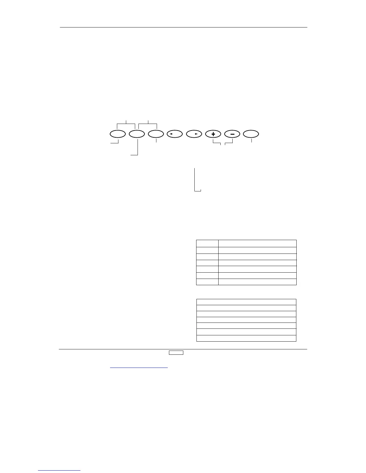
(4.13B)
Key Display
Switch display Switch lever position for mixing on
ON Mixing is always ON
MIX Mixing switch is forward, ON
FLP-D Flap switch is down position ON
FLP-U Flap switch is up position ON
BTFY0 Butterfly mixing switch is 0 position ON
BTFY1 Butterfly mixing switch is 1 position ON
(4.13C)
MIX
Mixing Switches available in each pr
ogrammable mix
1
On
⌫
MIX
⌫
FLP-D
⌫
FLP-G
2
On
⌫
MIX
⌫
BTFYO
⌫
BTFY1
3
On
⌫
MIX
⌫
BTFYO
⌫
BTFY 1
4
On
⌫
MIX
⌫
FLP-D
⌫
FLP-U
5
On
⌫
MIX
⌫
FLP-D
⌫
FLP-U
6
On
⌫
MIX
⌫
BTFYO
⌫
BTFY1
GLID
125