5-32
• In Maintenance Mode settings can be changed press and hold both and for 3
seconds or more to go to the mode.
• HDT and THS sentences cannot both be set at the same time for sensor throughput.
• Cannot be set for some bit rates (high rates) and output intervals (short intervals).
If this is the case, decrease the bit rate, increase the output interval, and decrease the
output sentences.
• Refer to "2.3 Cable Connection" for details regarding connecting external devices.
・Starting-up the display unit (turning the power on) while the sensor unit is unconnected
initializes HVE sentence (heaving sentence) settings. (The output cycle setting returns to
OFF.)
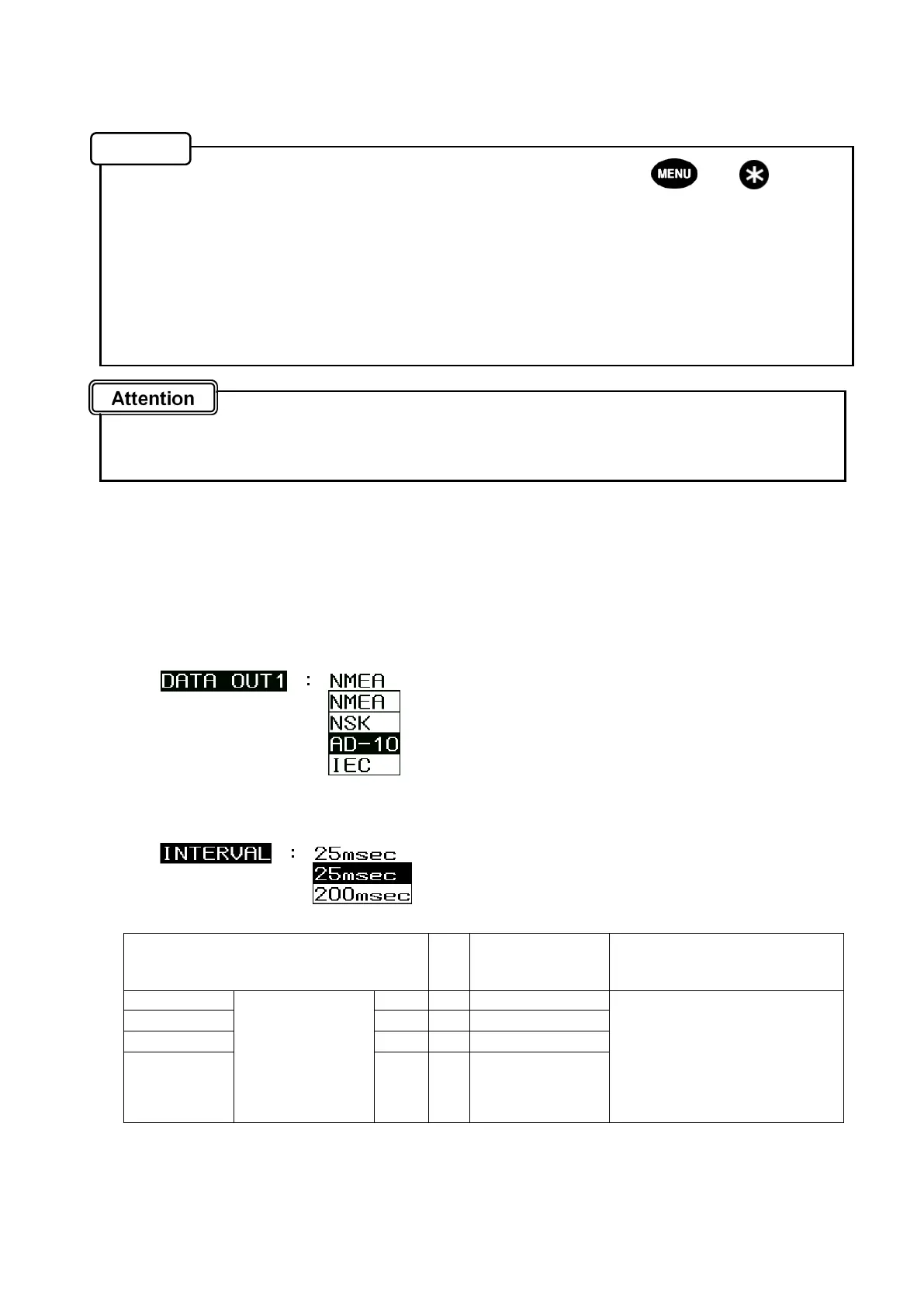
● Output of AD-10 format
AD-10 receiver (FR-14**, etc.) can be connected.
AD-10 format can be output from the following two ports (refer to p2-18,19 for detail).
INTERVAL (cycle) can be selected from 25msec and 200msec.
・DATA IN / OUT 1 connector: 3 thru 6 pin (Select “AD-10” in SENSOR THROUGH.)
・DATA IN / OUT 2 connector: 3 thru 6 pin (Select “AD-10” in DATA OUT1.)
Setting method (same as in SENSOR THROUGH)
1. Set “AD-10” for the data format.
2. Select 25msec or 200sec in INTERVAL.
For connecting to RADAR, select 25msec (Default is 25msec.)
Connecting method
DATA IN/OUT1 Connector
or
DATA IN/OUT2 Connector
Radar Note
3 (Orange) SENSOR
THROUGH
or
DATA OUT1
(TXD1,SCK1)※1
SD-A → DATA-H Select AD-10 in the
connection port setting
(SENSOR THROUGH or
DATA OUT1) and select
25msec or 200msec for the
output interval (Refer to the
above.)
4 (Yellow)
SD-B → DATA-C
5 (Green)
SC-A → SHIFT-H(CLK-H)
6 (Blue)
SC-B → SHIFT-C(CLK-C)
*1 AD-10 can output through the following 2 ports: Sensor Through port and Data OUT1 port (TXD1).
*2 Use CFQ-5374 (3m) or CFQ5374-15 (15m) for the cable (Refer to 2-26 and 2-27.)
Memo