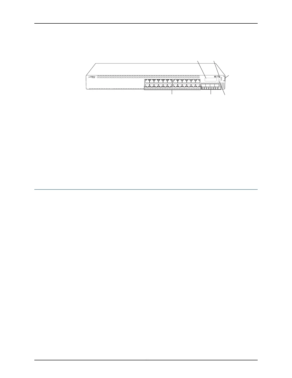
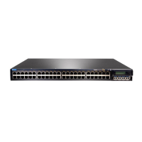
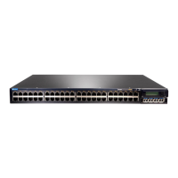
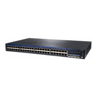
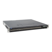
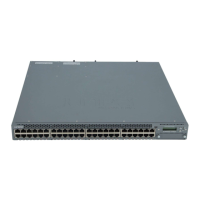
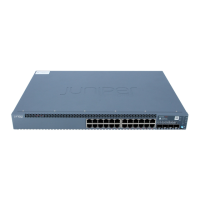
Figure 2: Front Panel of an EX3300 Switch with 24 Gigabit Ethernet Ports
g021217
0 1 2 3
ALM
EX3300
SYS
MST
LCD panel
Network ports
Chassis
status
LEDs
Enter buttonSFP+ uplink ports
Menu button
Related
Documentation
Chassis Status LEDs in EX3300 Switches on page 16•
• Network Port and Uplink Port LEDs in EX3300 Switches on page 17
• Network Port Connector Pinout Information for an EX3300 Switch on page 26
• Rear Panel of an EX3300 Switch on page 7
• EX3300, EX4200, and EX4500 Virtual Chassis Overview
• Installing a Transceiver in an EX Series Switch on page 79
• Removing a Transceiver from an EX Series Switch on page 115
• Installing and Connecting an EX3300 Switch on page 65
Rear Panel of an EX3300 Switch
The rear panel of the EX3300 switch consists of the following components:
•
Management Ethernet port
•
USB port
•
Console port
•
Protective earthing terminal
•
ESD point
•
Air intake or air exhaust, depending on the switch model
•
Serial number ID label
•
AC power cord inlet or DC power terminal block
Figure 3 on page 8 shows the rear panel of an EX3300 switch with AC power supply.
The power cord retainer extends out of the chassis by 3 in. (7.62 cm).
7Copyright © 2011, Juniper Networks, Inc.
Chapter 1: EX3300 Switch Overview



 To Next Page