Table 5: Chassis Status LEDs in an EX3300 Switch (continued)
State and DescriptionColorLED Label
•
On steadily—The switch is the master in the Virtual Chassis
configuration.
•
Blinking—The switch is the backup in the Virtual Chassis
configuration.
•
Off—The switch is a linecard member in the Virtual Chassis
configuration.
GreenMST (Master)
A major alarm (red) indicates a critical error condition that requires immediate action.
A minor alarm (amber) indicates a noncritical condition that requires monitoring or
maintenance. A minor alarm that is left unchecked might cause interruption in service or
performance degradation.
All three LEDs can be lit simultaneously.
Related
Documentation
Front Panel of an EX3300 Switch on page 6•
• Checking Active Alarms with the J-Web Interface
• Understanding Alarm Types and Severity Levels on EX Series Switches
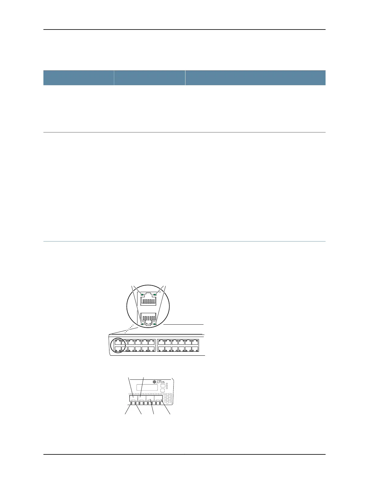
Network Port and Uplink Port LEDs in EX3300 Switches
Each network port and uplink port on the front panel of an EX3300 switch has two LEDs
that indicate link/activity and port status. See Figure 7 on page 17 and Figure 8 on page 17.
Figure 7: LEDs on the Network Ports on the Front Panel
0
1
2
3
4
5
6
7
8
9
10
11
12
13
14
15
16
17
18
19
20
21
22
23
g027005
0
1
Link/Activity LED Status LED
Figure 8: LEDs on the Uplink Ports
g021204
Link/Activity
LED
Status
LED
Port 0
Port 2
Port 3
Port 1
0 1 2 3
ALM
EX3300 PoE+
SYS
MST
17Copyright © 2011, Juniper Networks, Inc.
Chapter 2: Component Descriptions