6
1
KEB COMBIVERT F5-M / S12
Name: Basis
12.05.04
Chapter Section Page Date
© KEB Antriebstechnik, 2002
All Rights reserved
Functional Desription Operating and Unit Data
Adr.
min max
default
021Ah
ru.26 Active parameter set
1
-
-
70
The KEB COMBIVERT can fall back on 8 internal parameter sets (0-7). Through corresponding programming the inverter
can independently change parameter sets and is thus able to drive different operating modes. This parameter shows the
parameter set, with which the inverter is currently running. Independent of it another parameter set can be edited by bus
(also see chapter 6.8).
Adr.
min max
default
021Bh
ru.27 AN1 pre amplifier display
0,1
%
-
100-100
This parameter indicates the value of the analog signal AN1 in percent on the differential voltage input (terminal X2A.1 /
X2A.2) before signal amplification. In dependence on an.10 the indicated value 0...±100 % corresponds to: 0...±10 V;
0...±20 mA or 4...±20 mA (also see Chapt. 6.2 ÑAnalog inputsì).
Adr.
min max
default
021Ch
ru.28 AN1 post amplifier display
0,1
%
-
400-400
This parameter shows the value of the analog signal AN1 in percent after passing the characteristic amplifier. The range
of indication is limited to ±400 % (also see Chapt. 6.2 ÑAnalog inputsì).
Adr.
min max
default
0218h
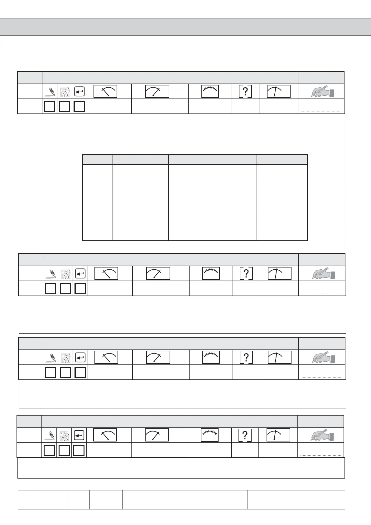
ru.25 Output terminal state
1
-
-
2550
Display of the currently set external and internal digital outputs. According to following table a certain decimal value is
given out for each digital output. If several inputs are set then the sum of their decimal values is displayed.
Bit -No. Decimal value Output Terminal
0 1 Out 1 (transistor output 1) X2A.18
1 2 Out 2 (transistor output 2) X2A.19
2 4 Out 3 (relais FLA,FLB,FLC) X2A.24...26
3 8 Out 4 (relais RLA,RLB,RLC) X2A.27...29
4 16 Out A (internal output A) none
5 32 Out B (internal output B) none
6 64 Out C (internal output C) none
7 128 Out D (internal output D) none

 Loading...


