28
TECHNICAL DATA 400V DEVICES
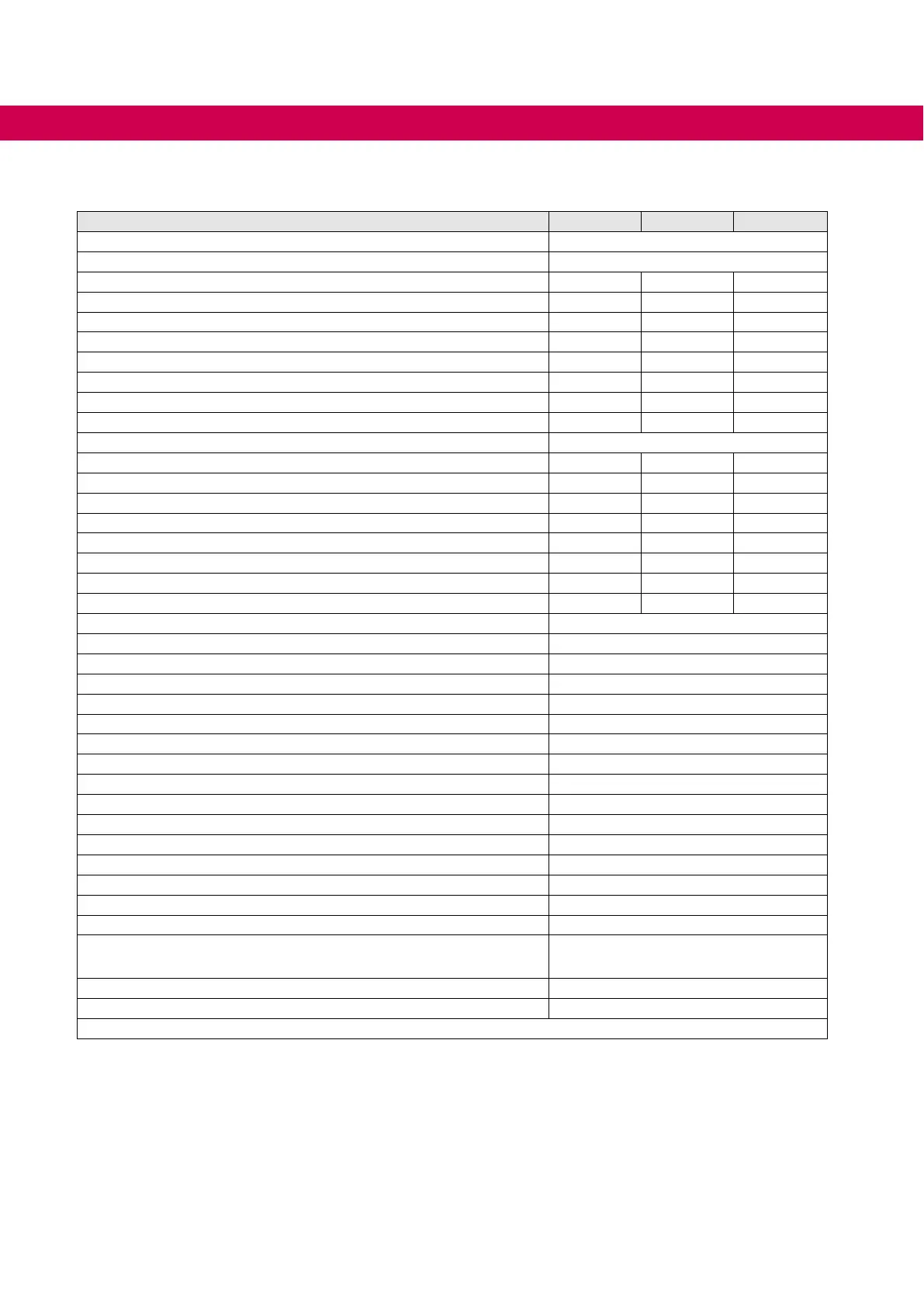
3.2 Technical data 400V devices
Device size 13 14 15
Housing C
Mains phases 3
Rated apparent output power S
out / kVA 8.3 11 17
Max. rated motor power P
mot / kW 5.5 7.5 11
Rated output current I
N / A 12 16.5 24
Rated output current UL I
N_UL / A 11 14 21
Max. short time current
1)
IHSR / % 180 180 150
Overcurrent
1)
IOC / % 216 216 180
Maximum current 0Hz/corner frequency fd at fS = 4 kHz
1)
If0/Ifd / % 100 / 180 100 / 180 100 / 180
Maximum current 0Hz/corner frequency fd at fS = 8 kHz
1)
If0/Ifd / % 100 / 180 70 / 160 70 / 150
Corner frequency f
d / Hz 6
Rated input current I
in / A 17 23 31
Rated input current UL I
in_UL / A 15.4 19.6 27
Rated input current DC
2)
Iin_dc / A 12.6 16.8 24.1
Rated input current UL DC
2)
Iin_UL_dc / A 10.4 13.8 19.8
Max. permissible mains fuse type gG I
_max / A 25 25 35
Rated switching frequency
3)
fSN / kHz 8 4 4
Max. switching frequency
3)
fS_max / kHz 8 8 8
Power dissipation at nominal operating
4)
PD / W 128 161 230
Power dissipation standby (no control release)
4)
PD_nop / W 20
Max. heat sink temperature T
HS /°C 82
Temperature for derating the switching frequency
5)
Tdr /°C 75
Temperature for uprating the switching frequency
5)
Tur /°C 70
Min. braking resistor R
B_min /Ω 39
Max. braking current I
B_max / A 21.5
Rated input voltage U
N / V 400 (UL: 480)
Input voltage range U
in / V 340…528 ±0
Mains frequency f
N / Hz 50 / 60 ±2
Rated input voltage DC U
N_dc / V 565 (UL: 680)
Input voltage range DC U
in_dc / V 480…746 ±0
DCswitch-olevel"Error!Underpotential“DC U
UP_dc / V 240
Switching level braking transistor DC U
B_dc / V 780
Switch-olevel"Error!Overpotential“DC U
OP_dc / V 840
Output voltage
6)
Uout / V 3 x 0…Uin
Output voltage at DC devices
6)
Uout_dc / V 3 x 0…Uin_dc /√2
Output frequency
3)
fout / Hz
0…400 (f
s = 4 kHz)
0…599 (f
s = 8 kHz)
Insulation resistance
@ Udc = 500 V Riso /MΩ 2
Minimum waiting period between two switch-on procedures
t / min 5
Table 7: Technical data 400V devices
1)
The values refer percentage to the rated output current IN.
2)
The values resulting from rated operation with B6 rectier circuit and mains choke 4 % UK.
3)
The output frequency is to be limited in such a way that it does not exceed 1/10 of the switching frequency.
Devices with higher max. output frequency are subject to export restrictions and are only available on request.
4)
Rated operation corresponds to UN = 400 V; fSN; fout = 50 Hz (typically value).
5)
On reaching the temperature Tdr the switching frequency is step down. The switching frequency is in-
creased again on cooling down to temperature Tur.
6)
The voltage at the motor is dependent on the series-connected units and on the control method,
=>
„4.3 Calculation of the motor voltage“.

 Loading...


