36
CONNECTION OF THE POWER UNIT
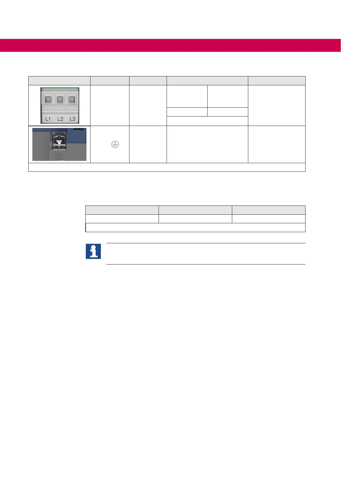
4.2.1.2 Line terminal strip X1A
X1A Name Function Cross-section
Tightening torque
L1, L2, L3
Mains con-
nection
3-phase
AWG without
wire-end
ferrule
mm² with
wire-end
ferrule
1.2…1.5 Nm
12 lb-inch
20...8 2,5...10
stranded wire
PE,
Connection
for
protective
earth
Screw M4
for ring crimp connector
1.3 Nm
11 lb inch
Figure 9: Line terminal strip X1A
4.2.2 Leakage currents
Calculated maximum leakage currents depending on voltage and frequency.
Rated input voltage / V Frequency / Hz Leakage current / mA
400 50 / 60 < 5
Table 8: Leakage currents
The specied leakage currents are calculated values according to DIN EN
60939-1. The real leakage currents may deviate from the calculated values
depending on the network conditions.

 Loading...


