40
CONNECTION OF THE POWER UNIT
4.2.5.7 Terminal block X1B motor connection
X1B Name Function Cross-section Tightening
torque
U, V, W
Motor connec-
tion
AWG without
wire-end
ferrule
mm² with
wire-end
ferrule
1.2…1.5 Nm
12 lb-inch
20...8 2.5...10
stranded wire
PE,
Connection for
protective earth
Screw M4
for ring crimp connector
1.3 Nm
11 lb inch
Figure 13: Terminal block X1B motor connection
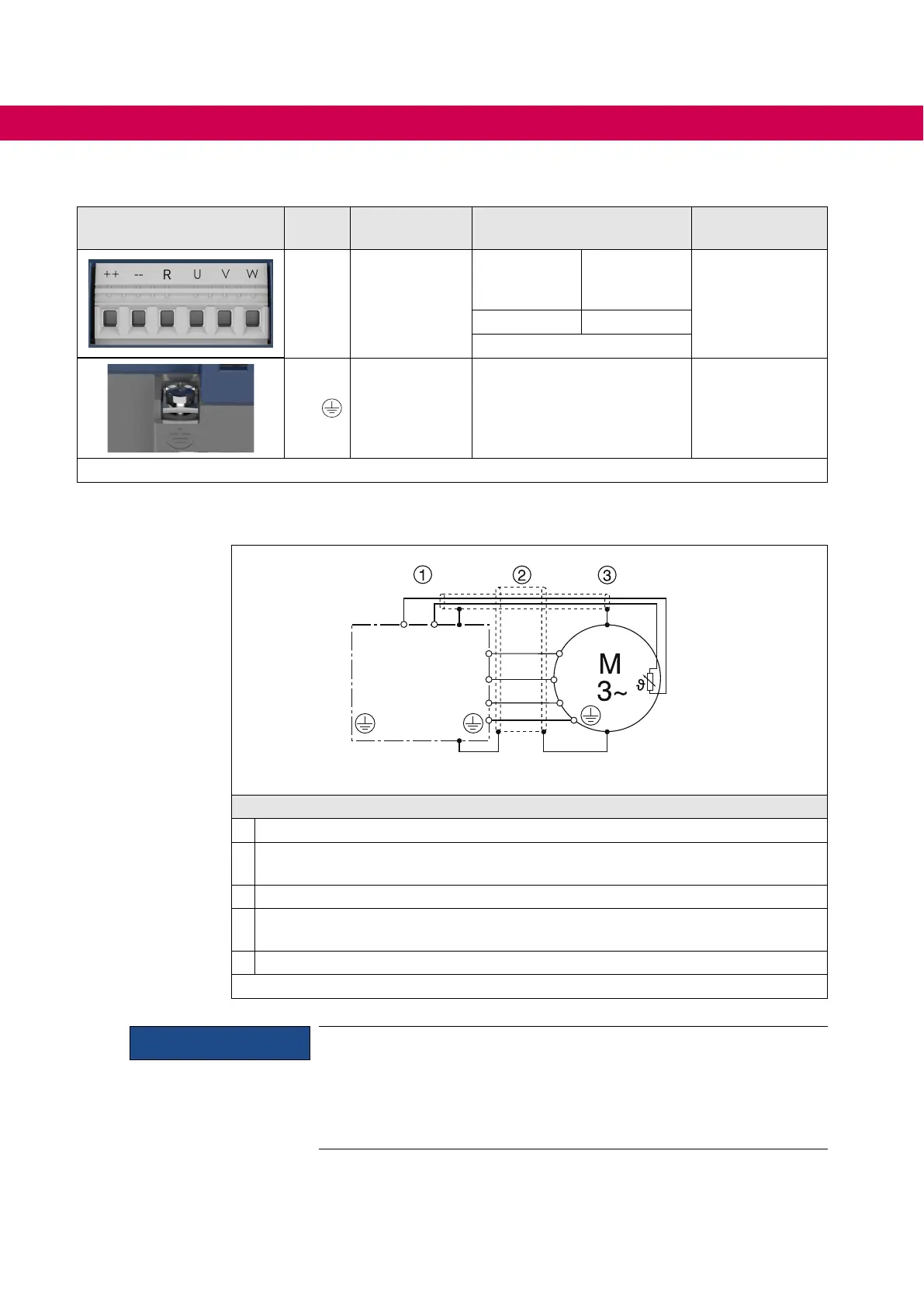
4.2.5.8 Wiring of the motor
L1
L2
L3
U
V
W
U
V
W
T1 T2
➃
➄
Legend
1 KEB COMBIVERT
2
Apply motor cable, shielding on both sides over a large surface on the motor
housing
3 Three-phase motor
4
Temperature monitoring (optional)
=> „4.2.7 Connection of a temperature detection“
5
Connection via shield plate (if not available, place on mounting plate)
Figure 14: Wiring of the motor
NOTICE
Ensure correct laying of the PTC cables !
• Do not lay PTC cable of the motor (also shielded) together with con-
trol cable !
• PTC cable inside the motor cable only permissible with an addition-
ally shielding (double shielding) !

 Loading...


