38
CONNECTION OF THE POWER UNIT
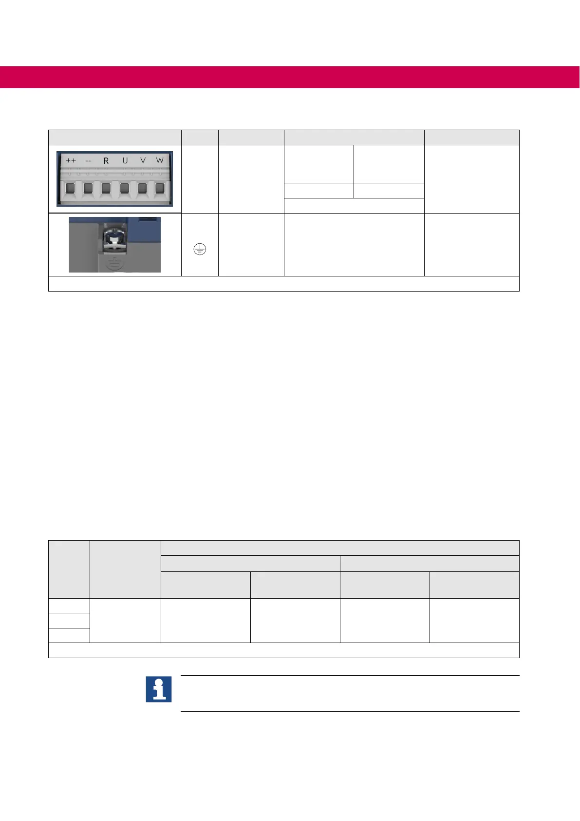
4.2.4.2 Terminal block X1B DC connection
X1B Name Function Cross-section
Tightening torque
++, -- DC input
AWG without
wire-end
ferrule
mm² with
wire-end
ferrule
1.2…1.5 Nm
12 lb-inch
20...8 2,5...10
stranded wire
PE,
Connection
for
protective
earth
Screw M4
for ring crimp connector
1.3 Nm
11 lb inch
Figure 12: Terminal block X1B DC connection
4.2.5 Connection of the motor
4.2.5.1 Selection of the motor cable
The correct cabling as well as the motor cable play an important part in case of low pow-
er in connection with long motor line lengths. Ferrite cores and low-capacitance cable
(phase/phase < 65 pF/m, phase/screen < 120 pF/m) at the output have the following
eects:
• Longer motor cable lengths
• Less abrasion of the motor gearbox by leakage currents
• Better EMC properties
4.2.5.2 Cable-fed disturbances depending on the motor cable length at AC supply
The maximum motor cable length is depending on the capacity of the cable as well as
on the EMC emitted interference. The following data apply for operation under rated
conditions.
Size Voltage / V
Max. motor cable length shielded in accordance with EN 61800-3
Category C1 Category C2
Motor cable / m
(standard)
Motor cable / m
(low-capacitance)
Motor cable / m
(standard)
Motor cable / m
(low-capacitance)
13
400 25 50 50 10014
15
Table 9: Cable-fed disturbances depending on the motor cable length at AC supply
Thecablelengthcanbesignicantlyextendedbyusingmotorchokesorlters.
KEBrecommendstheuseofmotorchokesorltersforalinelengthupto50m.
Motorchokesorltersareabsolutelynecessaryupto100m.

 Loading...


