29
TECHNICAL DATA 400V DEVICES
The technical data are for 2/4-pole standard motors. With other pole numbers
the drive controller must be dimensioned onto the rated motor current. Contact
KEB for special or medium frequency motors.
The service life of the drive controller with voltage DC link depends on the current load
of the electrolytic capacitors in the DC link. The use of mains chokes can increase the
service life of the condensators to a considerable extent, especially when connecting to
„hard“ power systems or when under permanent drive load (continuous duty).
The term "hard" power system means that the nodal point power (S
net) of the mains is
very high (>> 200) compared to the rated apparent output power of the drive controller
(Sout).
k =
S
net
>> 200 e.g. k =
2 MVA (supply transformer)
= 303 ––> Choke required–––– –––––––––––––––––––––
S
out 6.6 kVA (12G6)
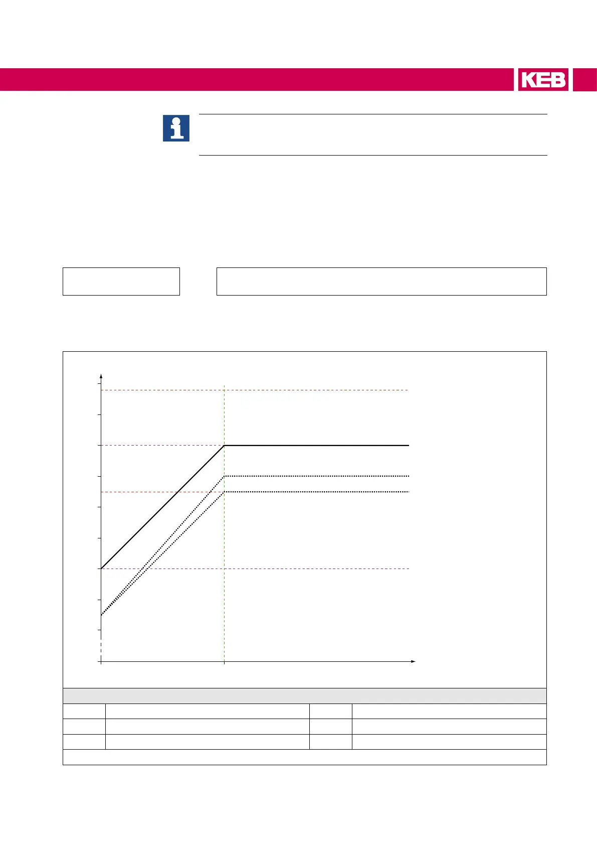
3.2.1 Overload and derating
80
60
100
120
140
160
180
200
220
fd (6Hz)f
0 (0Hz)
f
out / Hz
I
N / %
IHSR (13/14.G6) IOC (15.G6)
IN
IOC (13/14.G6)
IHSR (15.G6)
14.G6 (8 kHz)
15.G6 (8 kHz)
13.G6 (4/8 kHz) & 14/15.G6 (4kHz)
Legend
I
N Rated current fout Output frequency
I
OC Overcurrent f0 Standstill
I
HSR Hardware current limitation fd Corner frequency
Figure 1: Maximum load and derating depending on the switching frequency

 Loading...


