34
OVERVIEW OF THE COMBIVERT G6
4 Installation and Connection
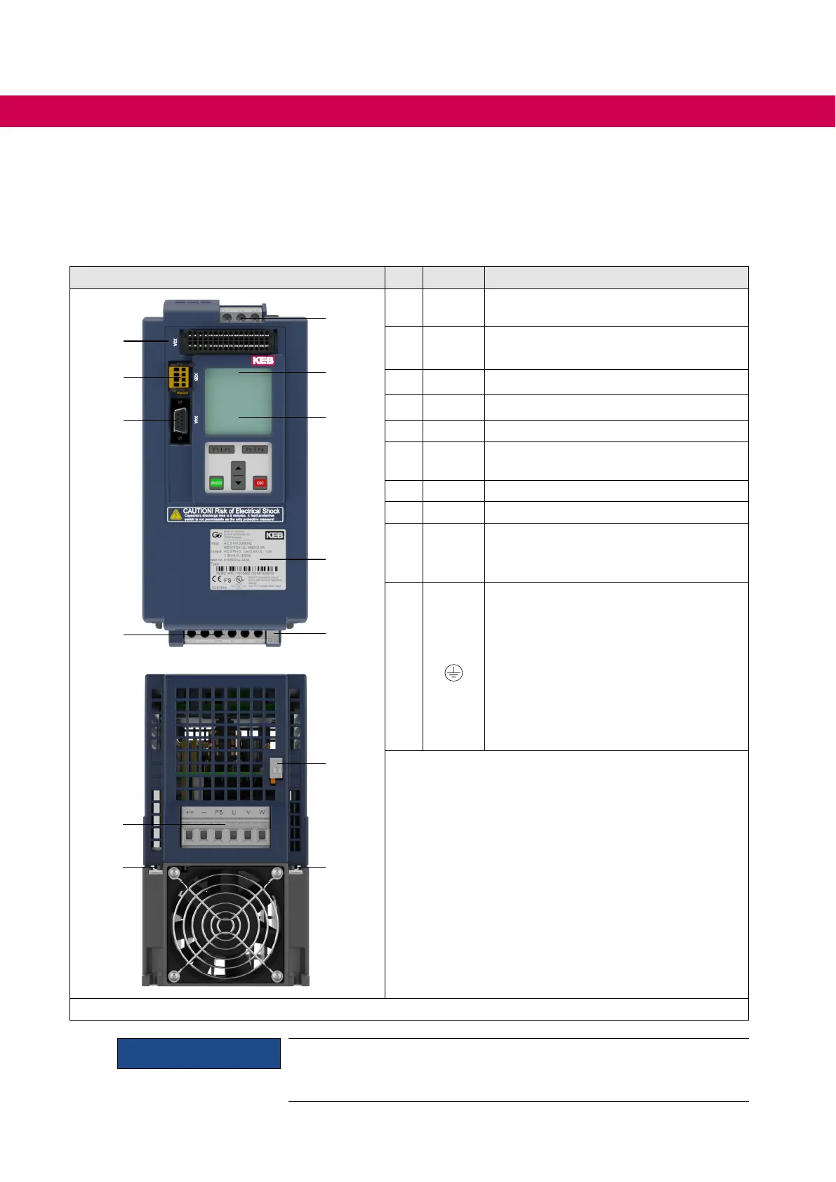
4.1 Overview of the COMBIVERT G6
Housing C No. Name Description
6
5
4
1
7
9
2
3
8
9
1
1010
1
X1B
Terminal block for three-phase motor ,
braking resistor and DC supply
2
X4A
Diagnostic interface
RS232/485 interface with DIN66019-II
3
X2B Safety function STO (optional)
4
X2A Control terminal strip 32-pole
5
X1A Mains input 3-pole
6
LED1
Drive controller state
(if no operator is available)
7
– Operator with display and keyboard
8
– Nameplate
9
X1C
Temperature monitoring;
Connection for external PTC or
temperature switch
10
PE,
Protective earth;
at connection to protective earth each
terminal may be assigned only once.
The shielding e.g. from the motor cable
is laid on the mounting plate in the
control cabinet or on the mounting kit
(optionally available).
=> „5.1 Mounting kit shield connection
braket“
Figure 7: Overview of the COMBIVERT G6
NOTICE
Ferrite rings required !
To comply with the limit values it is absolutely necessary to use the
supplied ferrite rings. => „5.2 Ferrit rings“

 Loading...


