Project design
© KEB, 2008-02 COMBIVERT R6-S Page 6.1 - 3
6
6. Project Design
The following chapter shall assist you in the planning stage of applications.
6.1 General designs
6.1.1 Control cabinet design calculation
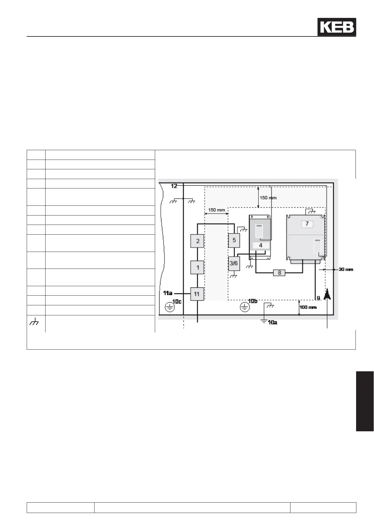
1 Main fuse
2 Main contactor
3 Commutationchokeorharmoniclter
4 COMBIVERT R6
5
HFside-mountedlter(≥ size 25)
HFside-mountedlter(≤size19)
7 Frequency inverter
8 if necessary external DC fuses
9 Motor lines
10 A Protective Earth (PE) on the moun-
ting plate power circuit
10b Protective Earth (PE) on the moun-
ting plate control circuit
10c Equipotential bonding with the
housing earth
11 Mains connection power circuit
11 A Mains connection control circuit
12 Control lines
Large area contact at the mounting
plate
Control circuit Power circuit Direction of the cooling
ns
 Loading...

