Parameter overview
© KEB, 2008-02 COMBIVERT R6-S Page 3.1 - 3
3
10
3. Functions
3.1 Parameter overview
3.1.1 Parameter list R6-S
Legend
Parameter: Parameter group, number and name (sorted acc. to parameter group and number)
Addr.: Parameter address in hex
R: Password level rw => write and read, ro => only readable
P: p => set-programmable; np => not set-programmable
E: E => Enter parameter
Lower limit: Minimum value (standardized);
the non-standardized value results by division by the reso-
lution
Upper limit: Maximum value (standardized);
Step: Step size, resolution
Default: Default value (standardized); the non-standardized value results by division by the resolution
LTK=>thedefaultvalueisdependentonthepowercircuitidentication
Unity: Unity
Reference: furtherinformationtothisparameteronspeciedpage(notchapter)
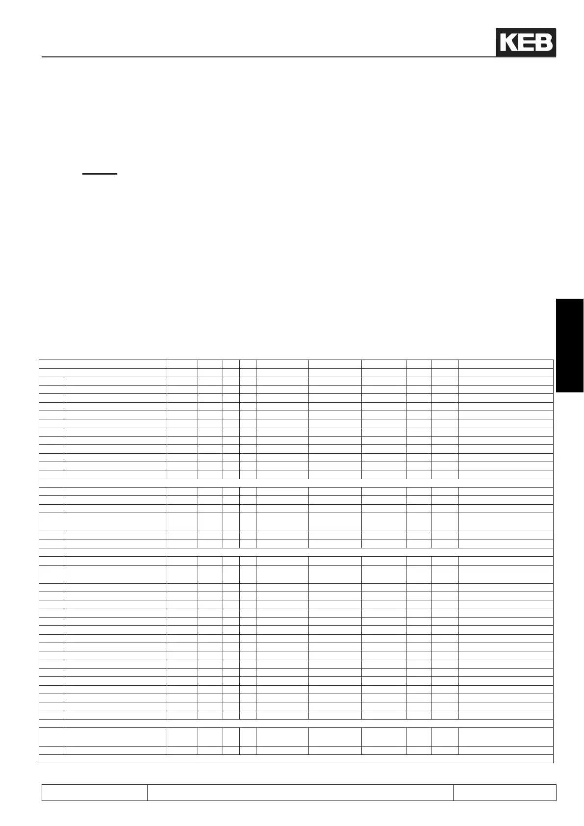
Parameter Addr. R P E Lower limit Upper limit Default Step Unity Reference
An.31 ANOUT1 function 0A1Fh rw p E 0 26 2 1 --- 3.3-3, 3.3-4
An.32 ANOUT1 value 0A20h rw p --- -100,0 100,0 0,0 0,1 % 3.3-3, 3.3-4, 3.3-6
An.33 ANOUT1 gain 0A21h rw p --- -20,00 20,00 1,00 0,01 --- 3.3-3, 3.3-5, 3.3-6
An.34 ANOUT1 offset X 0A22h rw p --- -100,0 100,0 0,0 0,1 % 3.3-5, 3.3-6
An.35 ANOUT1 offset Y 0A23h rw p --- -100,0 100,0 0,0 0,1 % 3.3-5
An.41 ANOUT3 function 0A29h rw np E 0 26 12 1 --- 3.3-3, 3.3-4, 3.7-3
An.42 ANOUT3 value 0A2Ah rw np --- -100,0 100,0 0,0 0,1 % 3.3-6
An.43 ANOUT3 gain 0A2Bh rw np --- -20,00 20,00 1,00 0,01 --- 3.3-5
An.46 ANOUT3 period 0A2Eh rw np E 1 240 1 1 s 3.3-3, 3.3-4, 3.4-13
An.47 ANOUT4 function 0A2Fh rw np E 0 26 12 1 --- 3.3-4
An.48 ANOUT4 value 0A30h rw np --- -100,0 100,0 0,0 0,1 % 3.3-6
An.49 ANOUT4 gain 0A31h rw np --- -20,00 20,00 1,00 0,01 --- 3.3-5
An.52 ANOUT4 period 0A34h rw np E 1 240 1 1 s 3.3-4, 3.4-13
cS.00 choke rated voltage 0F00h rw np --- 0 1000 variable 1 V 3.5-3, 4.2-3
cs.01 data commutation choke 0F01h rw np --- 0 5000 variable 1 A 3.5-3, 4.2-33
cS.02 regeneration level 0F02h rw np --- 100 120 103 1 % 3.2-6, 3.5-4, 4.2-4
cS.03
mains frequency max. tole-
rance
0F03h rw np --- 0 5 5 1 % 3.6-7, 4.2-4, 5.1-3
cs.04 control angle 0F04h rw np --- 0 600 variable 1 --- 3.5-3, 3.5-5, 4.2-3, 4.2-4
cS.06 puls off level 0F06h rw np --- -10000 0 -8 1 kW 3.5-4, 4.2-4, 4.2-5
di.00 PNP / NPN selection 0B00h rw np E 0 1 0 1 --- 3.4-2, 3.4-4
di.01 select signal source 0B01h rw np E 0 4095 0 1 ---
3.2-16, 3.2-18, 3.4-3, 3.4-4,
3.4-5
di.02 digital input setting 0B02h rw np E 0 4095 0 1 --- 3.2-16, 3.2-18, 3.4-4, 3.4-5
di.03 digitalnoiselter 0B03h rw np E 0 127 0 1 ms 3.4-3, 3.4-6
di.04 input logic 0B04h rw np E 0 4095 0 1 --- 3.4-3, 3.4-6
di.05 input trigger 0B05h rw np E 0 4095 0 1 --- 3.4-3, 3.4-6
di.06 select strobe source 0B06h rw np E 0 4095 0 1 --- 3.4-3, 3.4-6, 3.4-7
di.07 strobe mode 0B07h rw np E 0 2 0 1 --- 3.4-3, 3.4-6, 3.4-7, 3.4-8
di.08 input strobe dependence 0B08h rw np E 0 4095 0 1 --- 3.4-3, 3.4-6, 3.4-7
di.09 reset input selection 0B09h rw np E 0 4095 3 1 --- 3.4-3, 3.4-8, 3.4-9
di.10 reset input slope sel. 0B0Ah rw np E 0 4095 3 1 --- 3.4-3, 3.4-8
di.11 I1 functions 0B0Bh rw np E -2^31 2^31-1 1 1 hex 3.4-3,3.4-8,3.4-9,3.4-10
di.22 ST functions 0B16h rw np E -2^31 2^31-1 128 1 hex 3.4-8, 3.4-9, 3.4-10
di.24 I1 + function
0B18h rw np E 0 6 0 1 --- 3.4-8, 3.4-9
di.35 ST + function 0B23h rw np E 0 6 0 1 --- 3.4-8, 3.4-9
di.36 software ST input sel. 0B24h rw np E 0 4095 0 1 --- 3.4-9, 3.4-10
di.37 ST lock input sel. 0B25h rw np E 0 4095 0 1 --- 3.4-9, 3.4-10
di.38 turn off ST delay time 0B26h rw np --- 0,0 10,0 0,0 0,1 s 3.4-9, 3.4-10
do.00 condition 0 0C00h rw p E 0 92 20 1 ---
3.2-8, 3.4-12, 3.4-13,
3.4-14
do.01 condition 1 0C01h rw p E 0 92 3 1 --- 3.2-8, 3.4-15
further on next side

 Loading...
