Analog outputs
© KEB, 2008-02 COMBIVERT R6-S Page 3.3 - 3
3
10
3.3 Analog output
3.3.1 Short description analog output
The KEB COMBIVERT has one programmable analog output (ANOUT1). The variable which shall be output
at the outputs X2A.21 can be selected with An.31. ANOUT 3 and ANOUT 4 (An.41 / 47) can be output as
switching condition 42 or 43 with the digital outputs as PWM signal. The analog signal can be adapted to the
requirementswiththecharacteristicampliers(An.33...35 / 43...45 / 49...51). The ru parameters display the
actualsizebeforeandafteramplication.TheperiodforthePWMsignal can be adjusted with An.46/ 52.
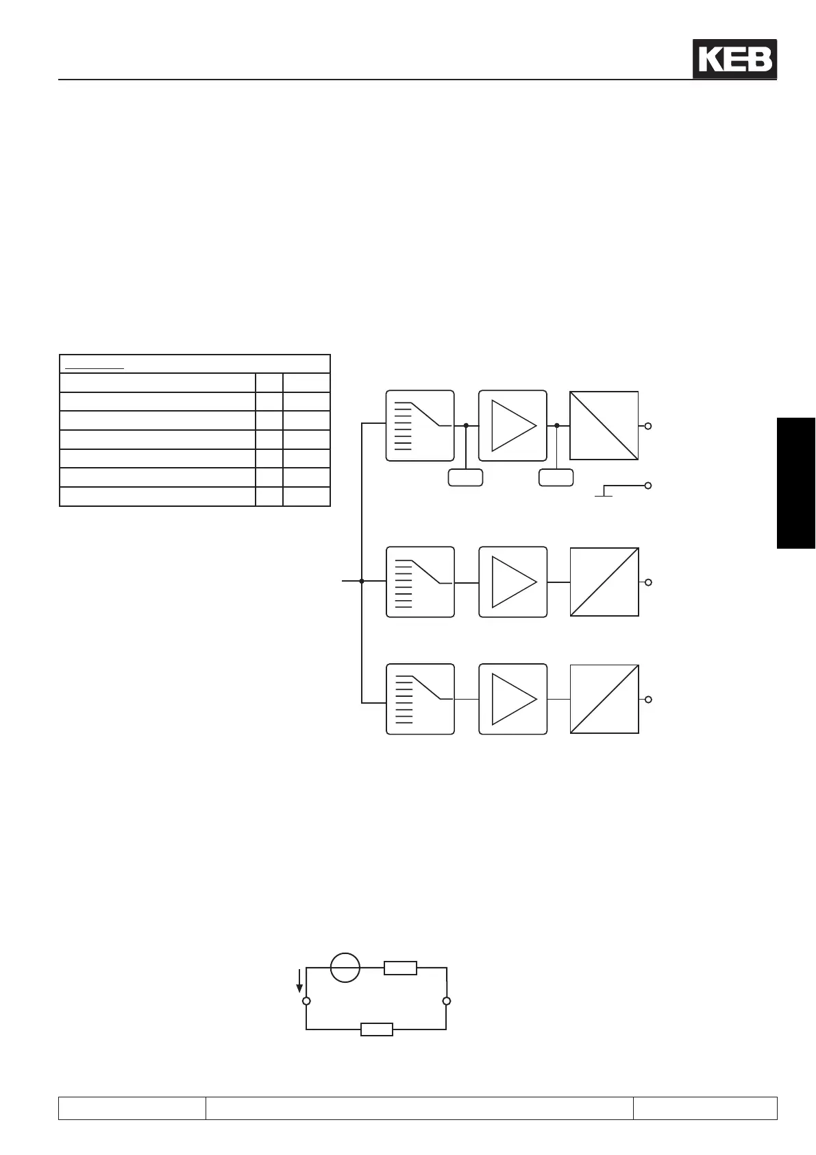
Picture 7.2.1 Principle of the analog outputs
An.31/41/47
Actual line frequencyΔ 2 ru.03
Ref. DC voltage 5 ru.18
DC current 6 ru.15
AC current 7 ru.17
Digital with An.32 / 42 / 48 8 An.xx
Power module temperature 12 ru.38
Actual power 26 ru.81
An.31
An.33
An.34
An.35
X2A. 21
ANOUT1
X2A. 23
AGND
0...±100%
0...±10V
ru.3 4ru.3 3
An.41
An.43
An.44
An.45
PWM
100%
An.46
An.47
An.49
An.50
An.51
PWM
100%
An.52
do.0...do.7
Wert “42”
do.0...do.7
Wert “43”
3.3.2 Output signals
ANOUT 1
A voltage of 0...±11,5 VDC displays the selected size in the range of 0...±115 % with a resolution of 10 bit at
the output. In order to compensate load-dependent voltage drops, the limitation at the output of the characte-
risticamplieris±115%.
Picture 7.2.2 Analog output
AGND
(X2A.23)
+-
ANOUT1 (X2A.21) /
U
out
= 0...±11,5 V
R
B
I
max
= 5mA
R
i
< 100
 Loading...

