Seite 3.4 - 8 COMBIVERT R6-S © KEB, 2008-02
Digital in- and outputs
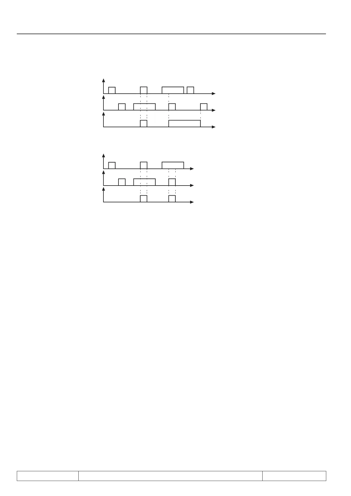
Picture 3.4.8.b Static strobe mode 1 (di.07 = 1)
Input signal
Strobe signal
Input state
Picture 3.4.8.c Static strobe mode 2 (di.07 = 2)
Input signal
Strobe signal
Input state
3.4.9 Reset / input selection (di.09) and neg. slope for reset inputs (di.10)
The reset input is set according to table 7.3.1 with di.09. If the reset input shall react to a negative slope, it can
be switched to negative slope evaluation with di.10 to one or several of the reset inputs speciedwithdi.09.
3.4.10 Assignment of the inputs
There are two fundamental different procedures for the assignment of the inputs.
a.) One or several inputs can be assigned to each function. That means, with the individual functions one
input can be selected which activates this function.
b.) One or several functions can be assigned to each digital input. That means, in parameters di.11...
di.22 „function“ and parameters di.24...di.35 „prog. function“ one or several functions can be assigned
to each digital input. With parameters di.11...di.22 several functions can be assigned to the respective
inputs, one function can only be selected with parameters di.24...di.35.
Both variants haveinuenceoneachother;ifaninputisassignedtoafunction,alsoparametersdi.11...di.22
and di.24...di.35 are adjusted accordingly.
Due to thetwovariantstheoperationhastwoadvantages:
- by the function-related programmingoftheinputsitcanalsobespeciedwhichinputsshallactivate
the function at parameterizing,
- by input-related displayyougetanoverviewofthecompletefunctionofaninputandnallyitcanbe
checked whether there are unwanted function overlaps.

 Loading...
