Seite 1.3 - 8 COMBIVERT R6-S © KEB, 2008-02
Hardware
1.3.1.7 Connection for precharging X1B
K1 Mains contactor
X1B Connection for precharging and switching-on of line
contactor K1
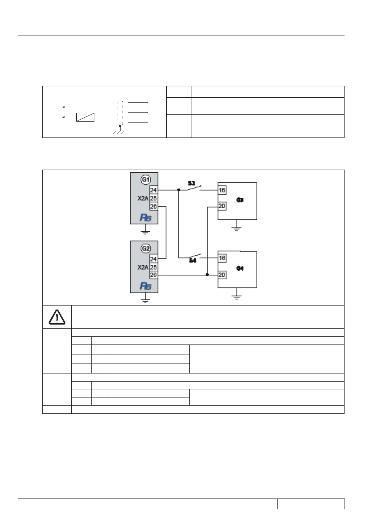
1.3.1.8 Connection of the control release of the connected inverter
A load draw in the DC circuit may be done only when the message „ready“ is set. This can be
guaranteed by a series connection of the relay R1 of the R6-S units with the control release of the
connected converters.
G1, G2 Regenerative unit COMBIVERT R6-S
X2A Control terminal strip
24
Relais 1 / NO contact
Ready for operation relay
25
Relais 1 / CO contact
26
Relais 1 / switching contact
G3, G4 Frequency inverter COMBIVERT F5
X2A Control terminal strip
16 Control release This terminal assignment refers only to one COM-
BIVERT F5
20 24V output
S3, S4 Control release for COMBIVERT F5

 Loading...
