Page 3.3 - 4 COMBIVERT R6-S © KEB, 2008-02
Analog outputs
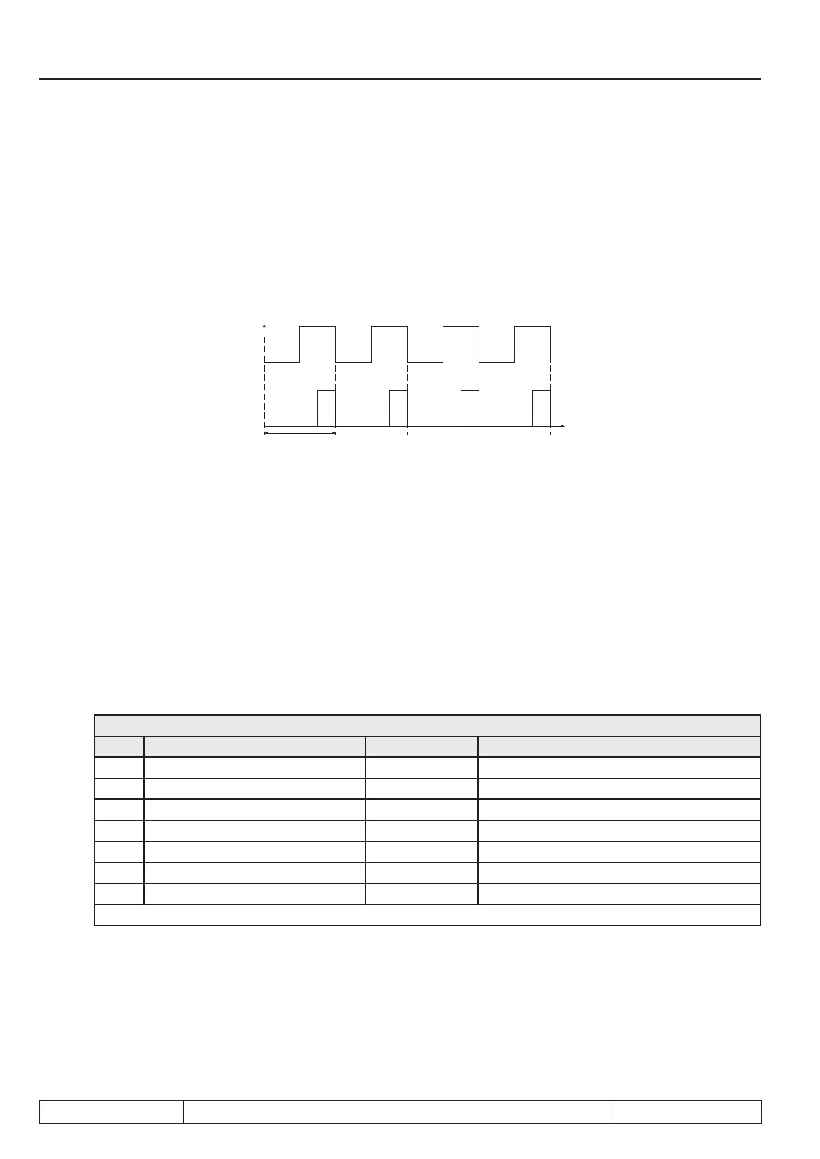
ANOUT 3 / 4, PWM outputs
Process variables that change only slowly e.g. the power module temperature, can be output via two virtual
analog outputs (ANOUT3 and 4). This is realized by generating a PWM signal (pulse width modulation) on a
digital output. The period T is adjustable with parameter An.46 or An.52 "ANOUT period" of 1 ...240 s.
Fig. 7.2.2.a PWM output signal
ANOUT 3/4
Input value 50 %
Input value 25 %
3.3.3 Analog output / display (ru.33...34)
The following parameters are used to display the analog outputs, before and after thecharacteristicamplier:
ru.33 ANOUT1 / pre ampl. display 0...± 400 %
ru.34 ANOUT1 / post ampl. display 0...± 115 %
3.3.4 ANOUT 1 Function (An.31 / An.36 / An.41, An.47)
Theseparametersdenethe process variable, which controls the respective output.Following adjustments
arepossible:
An.31 / An.41 / An.47
Value Function Standard An.31 10 V ≙ 100 %
2 Actual line frequency (ru.03) X 100% ≙ 1Hz
5 Reference DC voltage (ru.18) 100% ≙ 1000 V
6 DC current (ru.15) 100% ≙ 2x DC rated current (In.02)
7 AC current (ru.17) 100% ≙ 2x Supply rated current
8 Digital with An.32 / 42 / 48 0...100 %
12 Power module temperature (ru.38) 100% ≙ 100 °C
26 Actual power (ru.81) 100% ≙ 2x Regeneration rated actual power
Not listed values are not assigned.
 Loading...

