Seite 1.3 - 6 COMBIVERT R6-S © KEB, 2008-02
Hardware
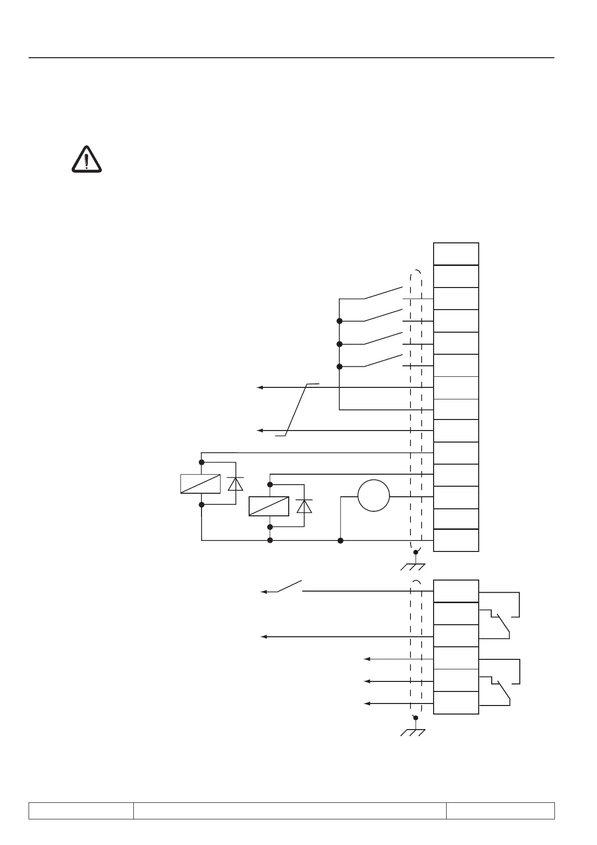
In order to prevent a malfunction caused by interference voltage supply on the control inputs, the following
directionsshouldbeobserved:
EMC
•
Use shielded/drilled cables
•
Lay shield on one side of the inverter onto earth potential
•
Lay control and power cable separately (about 10...20 cm apart); Lay crossings in a right angle
(in case it cannot be prevented)
U
X2A
10
11
12
13
14
15
16
17
18
16
18
19
20
21
22
23
24
25
26
27
28
29
max. 25 mA DC
per digital output
Analog output
0…±10 V DC / 5 mA
max. 30 V DC
0,01…2 A
max. 30 V DC
0,01…2 A
Active signal for further
R6-S units at parallel
operation
Supply voltage of the
inputs
Control release
 Loading...

