Seite 3.4 - 12 COMBIVERT R6-S © KEB, 2008-02
Digital in- and outputs
Description
To switch the digital outputs up to 8 conditions can be selected from different conditions. These are entered in
do.00...do.07.Theswitchingcondition0and1canbelteredwithdo.43anddo.44.Parameter ru.23 displays,
if one or several of these conditions are met. Now it can be selectedforeachag,whichofthe8conditions
shall be valid for it (do.16… do.23). Each condition can be inverted before the selection (do.08… do.15). As
standard all conditions (if several are selected) are OR-linked. It can be changed into AND-linkage i.e., all se-
lectedconditionsfortheagmustbefullled,inorderthattheagisset.Parameterru.24displaystheags
set in this level. do.33 ... 40 form a second logic level, wherebyaselectionofagsfromlogic level 1 can be
made.Eachagcanbeinverted with do.25 ... 32. do.41 adjusts the type of the linkage (AND/OR). Parameter
do.42 serves for inverting one or several outputs. The output signals are assigned to the terminals with do.51.
ru.80 displays the digital output state, ru.25 displays the output terminal state. The internal outputs OA...OD are
directly connected with the internal inputs IA...ID.
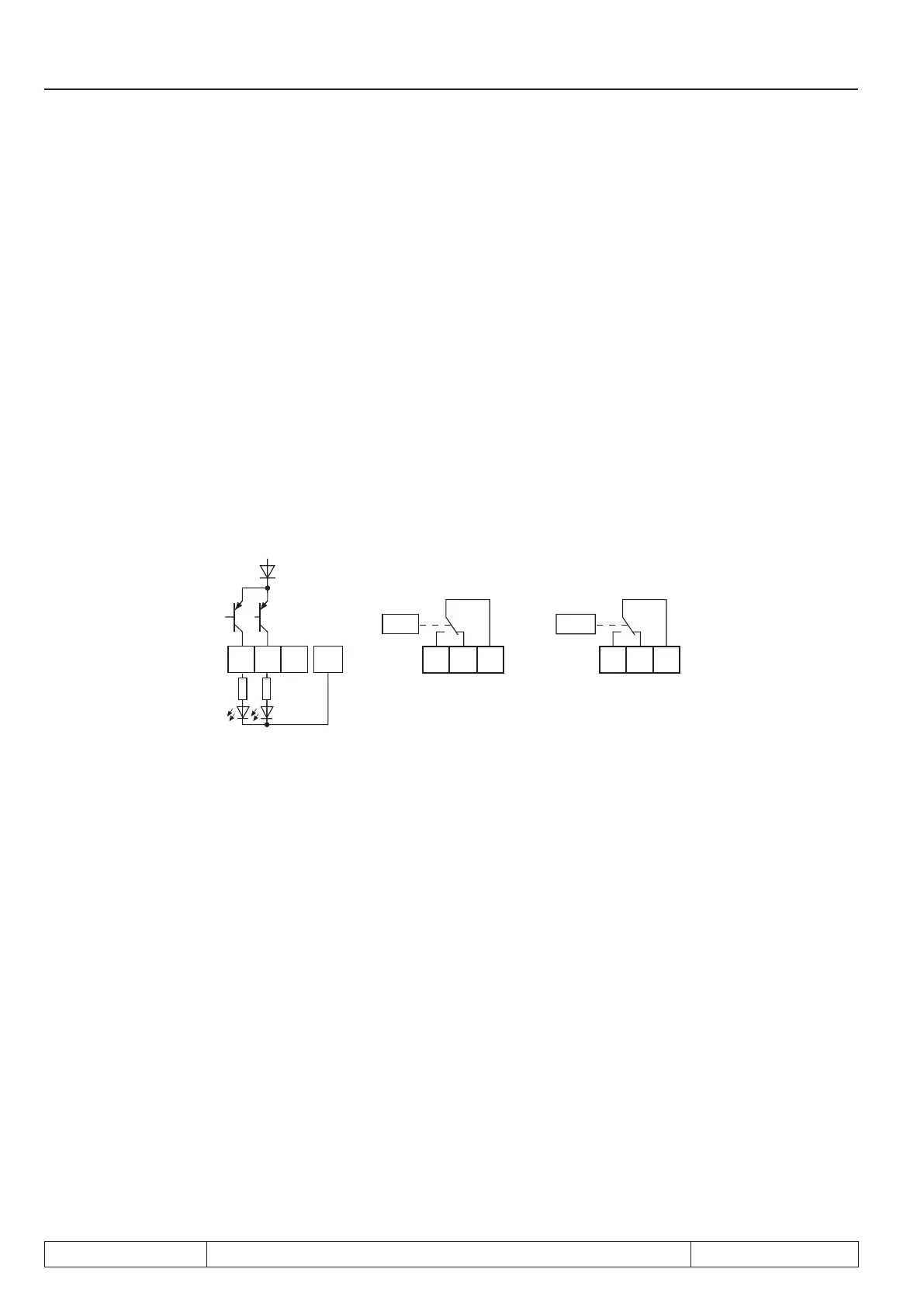
3.4.13Output signals / hardware
Picture 7.3.13a Transistor outputs Picture 7.3.13b Relay outputs
+24V / 50mA
X2A X2A X2A
O1
19
O2
20
Uout
17
COM
23
R1 R2
RLA
24
RLB
25
RLC
26
FLA
27
FLB
28
FLC
29
max. 30V / 0,01...2A max. 30V / 0,01...2A
The current of X2A.17, 19 is limited to 25mA. A protective wiring shall be provided at inductive load at the relay
outputs or transistor output (free-wheeling diode)!!
3.4.14 Output lter (do.43, do.44)
A ltercanbesetforswitchingcondition0withdo.43.Forswitchingcondition1withdo.44.Thechangeofa
switching condition must beappliedfortheltertime,thenitbecomesactiveattheoutputofthelter.Ifthe
change is cancelled duringltertime,theltertimeisresetandrestartatthenextchange.Theltertimecan
be adjusted in a range of 0 (off)...1000ms.

 Loading...
