32
1 Electrical installation
Operation Manual Supply Unit SO CM-P BG1+2
ID no.: 1400.201B.5-00 Date: 02/2020
Electrical installation
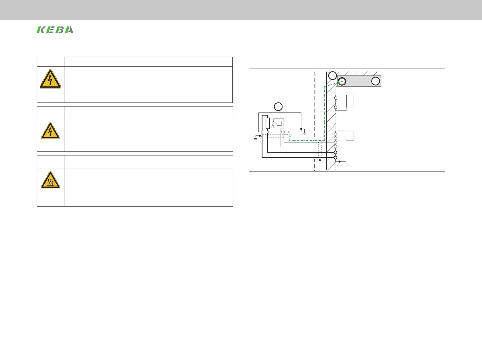
4.10.2 Connection example with ext. braking resistor
11
15
16
24 V
GND
BR
BR
ϑ
ϑ
X2
n.c.
n.c.
n.c.
X5.1
X3 X3
X4
X5.2
DC Link -
DC Link+
GND
+24 V
X1
PE
ϑ
L1 L2 L3 PEL1 N
PE
L3
L2
L1
L3.1
L2.1
L1.1
6
14
13
5
L3
L2
L1
L3.1
L2.1
L1.1
3
19
W
U
V
X12
Motor
3~
ϑ
3
2
2
W
U
V
X14
Motor
3~
ϑ
3
2
2
W
U
V
X13
Motor
3~
ϑ
3
2
2
BRK
ϑ
Motor
Schirmfahne
(11) Supply unit
(15) Ext. braking resistor
X1 Connection for braking resistor with
thermal contact (Klixon)
(16) Backing plate (earthed).
Figure 4.12 Connection, braking resistor with thermal contact (X1)
DANGER! Risk of injury due to electrical power!
Carelessness will result in serious injuries or death.
x Terminal BR is permanently connected to DC link potential (>300 V DC).
x Never make or disconnect electrical connections while they are electrically live! Always
disconnect the power before working on the device. Even 10min. after switching off the
mains supply, dangerously high voltages of ≥50V may still be present (capacitor charge). So
check that electrical power is not present!
CAUTION! Damage to the ext. braking resistor due to lack of temperature monitoring!
Carelessness can result in overheating of the ext. braking resistor.
x The ext. braking resistor must be monitored by the controller. The temperature sensor (Klixon) in
the braking resistor must have, as a minimum, basic isolation as per EN61800-5-1 in relation to
the body of the resistor at mains potential.
x In the event of overtemperature, the supply unit must be disconnected from the mains.
WARNING!
Damage to neighbouring assemblies and risk of injury due to hot surfaces on
the ext. braking resistor!
Carelessness may result in serious burns.
x Intensive thermal radiation is produced by the braking resistor (>300°C).
x For this reason maintain sufcient clearance to neighbouring assemblies or install the braking
resistor outside the switch cabinet.
x If the braking resistor is mounted outside the switch cabinet, please provide adequate protection
against touching that reliably protects against hot surfaces.
For technical data of the design of the braking resistors see chapter Appendix. The cable
cross-section is dependent on the braking resistor's power rating. The cables are to be
protected by suitable means.
 Loading...