43
1 Design variants
Operation Manual Supply Unit SO CM-P BG1+2
ID no.: 1400.201B.5-00 Date: 02/2020
Design variants
6.1.3 Protective earth conductor connection with 24 V back-up
on power failure
For these devices, the DC link in the 24 V switched-mode power supply (24V SMPS) is
coupled internally to the DC links in the axis controllers (DC Link +/-).
The DC link in the 24 V switched-mode power supply and the DC link in the axis
controller are fused separately on the mains side.
Therefore the minimum current carrying capacity of the PE conductor, formed by the
sum of the fuse rated currents for both mains connections, is also to be taken into
account for the design of the cross-section. Furthermore, the minimum requirements for
the devices not coupled as described in Section 4.4 apply.
6.2 Version with integrated braking resistor
Applies to SO CM-P.xxxx.11xx.x
6.2.1 Purpose of the design variant
In regenerative operation, e.g. when braking the drive, the motor feeds energy back
to the axis controller. This increases the voltage in the DC link. If the voltage exceeds
a threshold value, the internal braking transistor in the supply unit is activated and the
regenerated power is converted into heat by means of a braking resistor.
The design variant described here is a low-cost option for braking drives with low
masses without additional effort.
The integrated braking resistor also has the major advantage that no additional space for
an external braking resistor is required.
However, the braking power is limited for thermal reasons. You will nd the technical data
for the BG1 in section A.1.1 and for the BG2 in section A.2.1
6.3 Version without 24 V switched-mode
power supply
Applies to SO CM-P.xxxx.0xxx.x
6.3.1 Purpose of the variant
With this design variant you can supply the control section for the ServoOne CM system
using an existing switched-mode power supply.
The external switched-mode power supply must meet the following minimum
requirements:
y Uv = 24 V ± 10 %, stabilised and smoothed (operating voltage)
y Output power as per selected supply unit and axis controller connected
y Internal polarity reversal protection
y The power supply unit used must have safe and reliable isolation in relation
to the mains as per EN 50178 or EN 61800-5-1.
y The starting current for the control voltage can briey reach 2-3 times the
operating current.
y If other devices are supplied from this switched-mode power supply, the
power gures must be correspondingly higher.
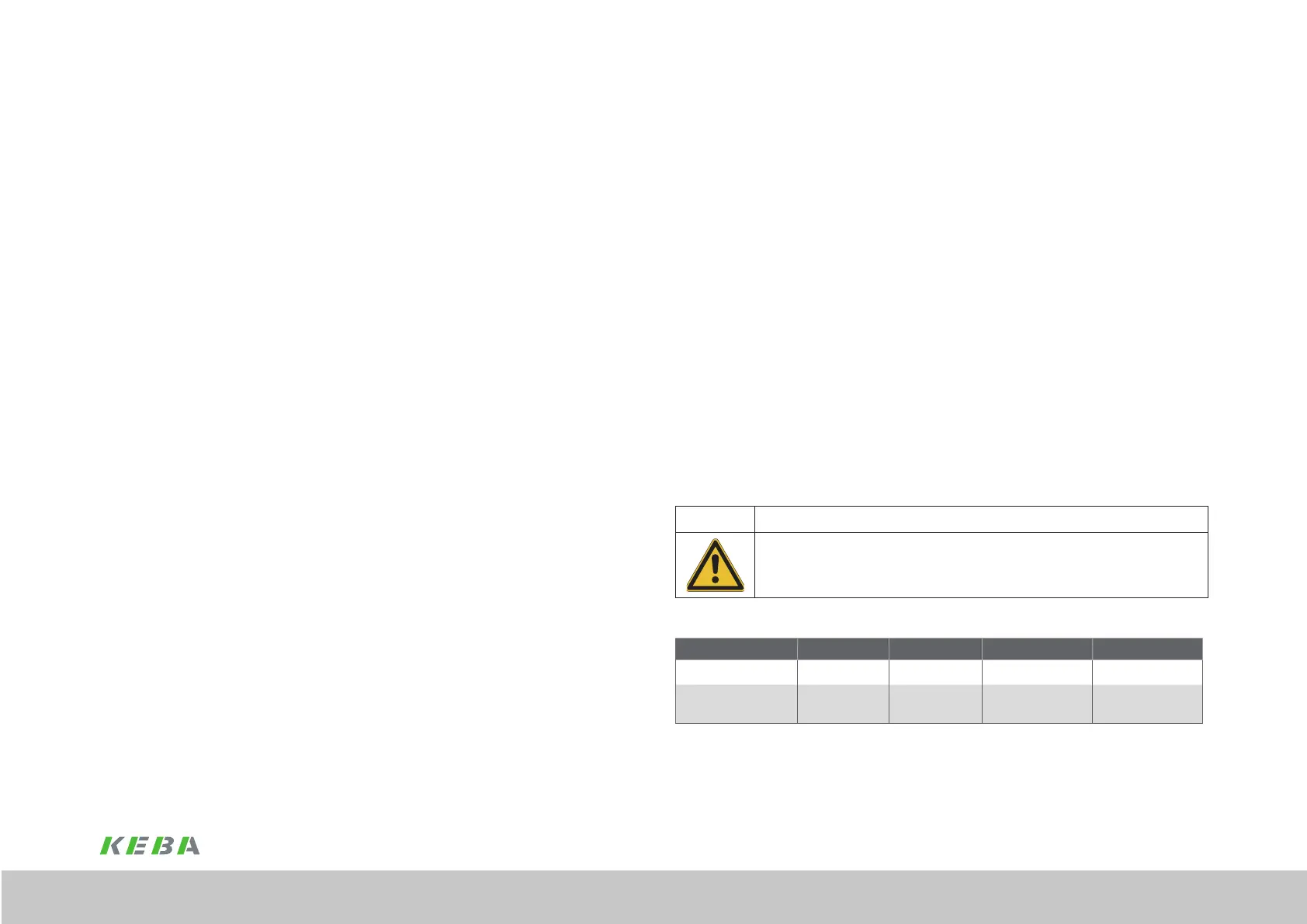
CAUTION! DAMAGE TO THE DEVICE DUE TO ERROR IN THE WIRING!
x Carelessness may result in signicant damage.
The connection 24 V/GND on the supply unit is at earth potential (see PELV). By connecting, e.g.
control cable shields other loads may be damaged. Please check connections rst.
Current consumption, 24 V control supply (A)
Device SOCM-P.0010 SOCM-P.0110 SOCM-P.0022 SOCM-P.0122
Cooling system Wall mounting Cold plate Wall mounting Cold plate
Current consumption, 24
V control supply
0.7 A 0.4 A 1.0 A 0.5 A
Table 6.2 Current consumption, 24 V control supply (A)

 Loading...