24
1 Electrical installation
Operation Manual Supply Unit SO CM-P BG1+2
ID no.: 1400.201B.5-00 Date: 02/2020
Electrical installation
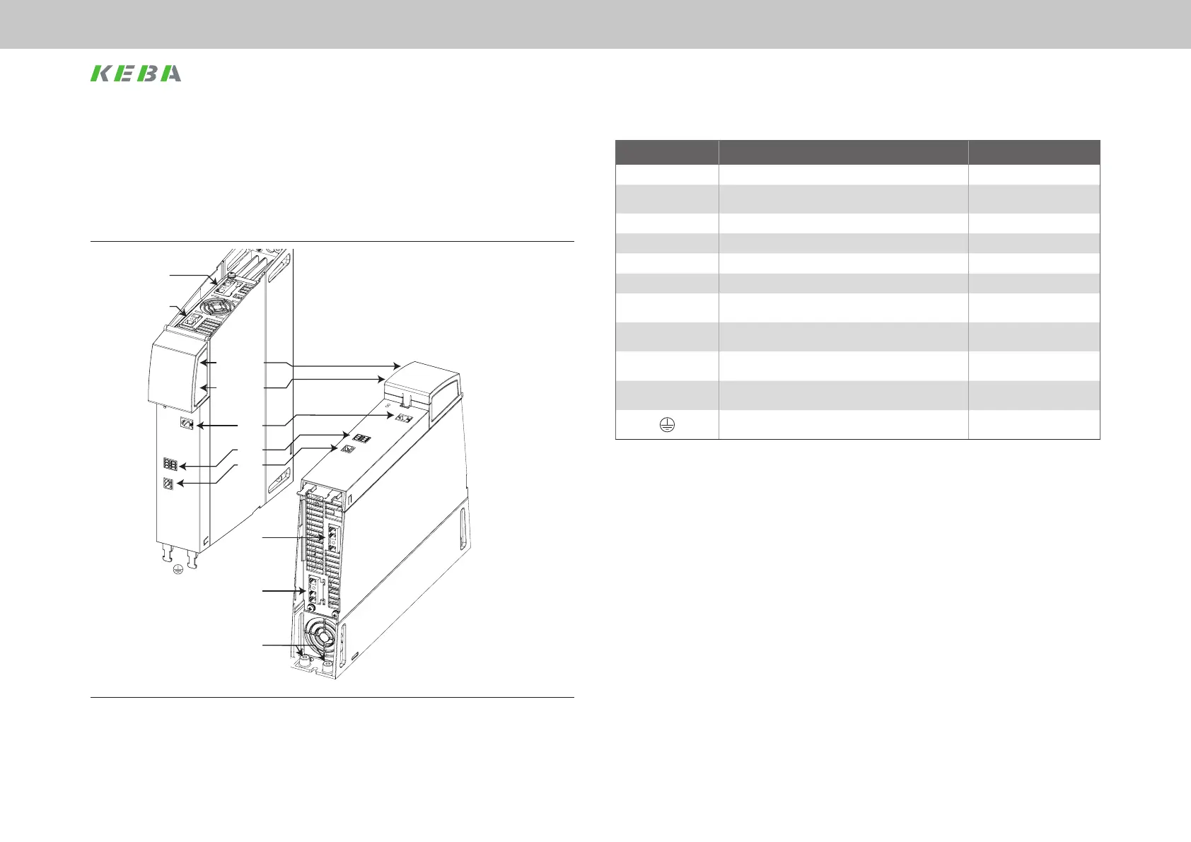
Abbreviation Designation Details
24 V DC / GND 24 V control supply output via busbars See Chapter 4.12
DC Link +/- DC link supply output via busbars See Chapter 4.12
X1 Connection for braking resistor See Chapter 4.10
X2 24V control supply output via terminals See Chapter 4.11
X3 Cross-communication output (XC out) See Chapter 4.13
X5 Relay contact (RO02), programmable See Chapter 4.13
X6
Relay contact (RO01)
Digital outputs (TPO1, TPO2)
See Chapter 4.13
X7
Switched-mode power supply mains input
(L1, L2 / 2 x 400 V AC)
See Chapter 4.8
X8
DC link supply mains input
(L1, L2, L3 / 3 x 230/400/480 V AC)
See Chapter 4.6
PE Protective earth conductor connection See Chapter 4.4
Shield connection, control cable
Table 4.1 Key to the ServoOne CM-P supply unit layout
4.3 Overview of the connections
The following shows the layout of ServoOne CM-P supply unit with the corresponding
positions of connectors and terminals. For improved clarity we have added an
abbreviation to the designation for the connectors and terminals.
X7
X1
X2
X3
24 V DC / GND
DC Link +/-
X6
X5
X8
PE
Figure 4.3 Layout, ServoOne CM-P supply unit
 Loading...