36
1 Electrical installation
Operation Manual Supply Unit SO CM-P BG1+2
ID no.: 1400.201B.5-00 Date: 02/2020
Electrical installation
4.14 Commissioning
You will nd a description of commissioning in the Operation Manual ServoOne CM Axis
Controller chapter4.
4.15 Connection examples, supply unit
The supply unit can be operated on supply systems with 3 x 230V, 3 x 400 V and 3 x
480 V. For connection examples, see next page.
NOTE:
A maximum of 8 axis controllers (this corresponds to maximum 24 axes) can
be connected and operated on one ServoOne CM-P Supply Unit .
NOTE:
Connections X3 are used only for internal communication between supply unit
and axis controller.
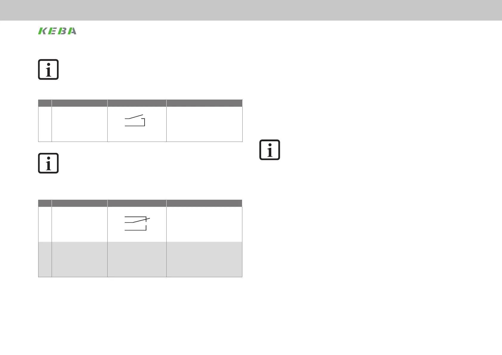
4.13.2 Specication, relay contact REL Output (X5)
Des. Term. Specication Details
X5
RO02NO = normally open
contact
Relay contact for low-voltage circuit:
≤ 250 V AC or ≤ 30 V DC, 1.5 A
max. each,
contact freely programmable
Factory setting = Operation of main
contactor
NOTE:
For switching inductive loads (e.g. auxiliary contactors) on X5, we recommend
the usage of suppressors (AC-operated contactors) or free-wheeling diodes
(DC-operated contactors) on their control coils.
4.13.3 Specication, connection "State" (X6)
Des. Term. Specication Details
X6
RO01NC = normally closed
contact
RO01CO = changeover
contact
RO01NO = normally open
contact
Signal relay contact for PELV circuit:
≤ 25 V AC or ≤ 30 V DC, 0.5 A max.
each (only ohmic load),
contact freely programmable
Factory setting = Active on error
X6
TP00 = test pulse signal
00
TP01 = test pulse signal
01
GND = reference ground
Signal driver outputs for
internal usage for short-
circuit and cross-circuit
checks on the wiring to
the safe inputs on the axis
controllers
See
Model Description SD0
ID no. 1400.402B.x-xx

 Loading...