35
1 Electrical installation
Operation Manual Supply Unit SO CM-P BG1+2
ID no.: 1400.201B.5-00 Date: 02/2020
Electrical installation
4.13 Control connections (front panel)
Step Action Comment
1.
Make a connection between the connection X3 on the supply unit
and X3 on the rst axis controller (cross-communication).
For this purpose use the cable
supplied of type: XCOM
See appendix
2.
If necessary wire the programmable relay contacts X5 and X6 as
well as the test pulse outputs TP01 and TP02.
3.
Check all connections again!
Figure Abbreviation Designation
X3
XC OUT
RO01NCTP00
RO01COTP01
RO01NO GND
X6 / State
ERR
Voltage
X5 / REL Output
RO02CO
RO02NO
LED red
(ERR)
Supply unit error status (ashing
code)
LED green
(Voltage)
Status mains supply available
X3 / XC OUT Cross-communication
X5 / REL Output Relay contact (RO02)
X6 /State
Relay contact (RO01)
Digital outputs (TPO1, TPO2)
Figure 4.16 Layout, supply unit front
4.13.1 Specication, cross-communication (X3)
Des. Term. Specication Details
X3 XC Out
Cross-communication output (RJ10 connector), internal
RS485 network for communication with axis controllers
See
Operation Manual SO CM
ID. no. 1400.200B.x-xx
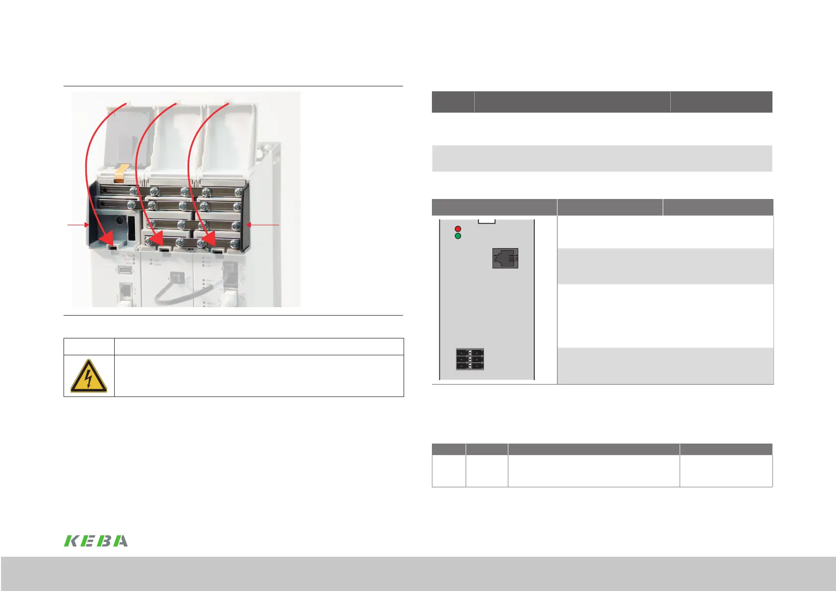
4.12.3 Overview of busbars in the group
A
Figure 4.15 Cover on the busbars
WARNING! Risk of injury due to electrical power!
Carelessness may result in serious injuries or death.
x The multi-axis system is only allowed to be operated with the cover on the busbars closed! It
is also important that the side covers (A) are tted. Both provide protection against touching
bare and live parts.

 Loading...