34
1 Electrical installation
Operation Manual Supply Unit SO CM-P BG1+2
ID no.: 1400.201B.5-00 Date: 02/2020
Electrical installation
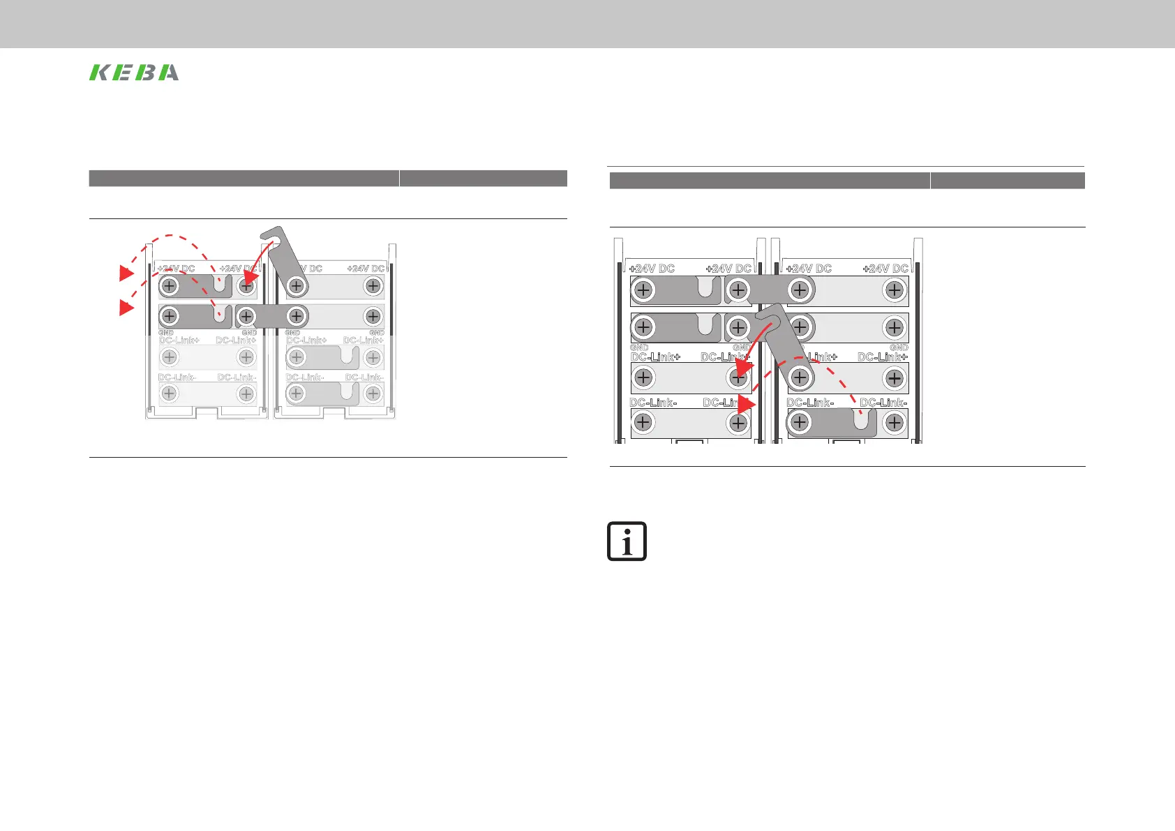
4.12.2 DC link supply
Figure Specication
ServoOne CM-P
supply unit
ServoOne CM
axis controller
x ServoOne CM-P supply unit
x DC link voltage 565/ 678V DC
x Depending on mains voltage
(400 V / 480 V)
x Tightening torque 2.1 Nm
Figure 4.14 DC link supply
NOTE:
The software for the supply unit must be set to the mains voltage connected.
This action is necessary so that all switching thresholds (e.g. under/overvolt-
age, switching on the brake chopper etc.) are set correctly. Details can be
found in the ServoOne CM device help.
4.12.1 24 V control supply
Figure Specication
ServoOne CM-P
supply unit
ServoOne CM
axis controller
to
MotionOne CM
control
x U
St
=+24VDC ±20 % stabilised
and smoothed
x Continuous output power of the
switched-mode power supply
(SMPS) max. 470 W
x Internal polarity reversal
protection
x The power supply unit used must
have safe isolation in relation to
the mains as per EN61800-5-1
x Tightening torque for the busbar
ttings 2.1 Nm.
Figure 4.13 Busbars, 24 V control supply
 Loading...