45
1
Operation Manual Supply Unit SO CM-P BG1+2
ID no.: 1400.201B.5-00 Date: 02/2020
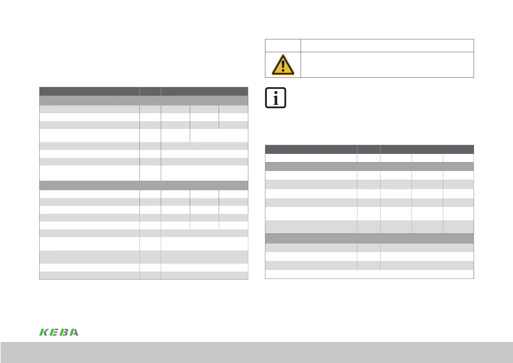
CAUTION! DAMAGE TO THE DEVICE DUE TO OVERLOAD IN THE DC LINK!
x Carelessness may result in signicant damage.
The maximum overall capacitance of the multi-axis system DC link must not exceed the value
stated.
NOTE:
In the overall axis group, a DC link capacitance of ≥ 100µF/kW (for 3 x 400V)
or ≥ 170µF/kW (for 3 x 230V), referred to the highest rated power that
occurs, must be provided. This capacitance is determined by adding together
the capacitances of the individual devices. The root mean square of the active
power for a load cycle is dened as the active power.
A.1.1 Technical data, brake chopper BG1
Device Unit SOCM-P.0010 / SOCM-P.0110
Mains voltage V AC 230 400 480
Brake chopper power electronics
Brake chopper switching threshold V 411 652 765
Overvoltage protection V 446 687 800
Continuous braking power [kW] kW 1.8 3 3
Peak braking power for maximum 0.5 s *) kW 8 13 16
Maximum ohmic resistance of an externally
installed braking resistor
Ω 60 90 90
Minimum ohmic resistance of an externally
installed braking resistor
Ω 21 33 38
Supply unit with integrated braking resistor: (model SO CM-P.xxxx.11xx.x)
Continuous braking power W 75
Peak braking power for maximum 0.5 s *) kW 3
Ohmic resistance of the integrated braking resistor
Ω
56
*) After this time shutdown is initiated based on I
2
x t
Table A.2 Brake chopper BG1
A Appendix
A.1 Technical data, supply unit BG1
Device Unit SOCM-P.0010 / SOCM-P.0110
Input, mains side
Mains voltage U
N
± 10%, 3 times V AC 230 400 480
Continuous current [A
AC eff
], typical A
eff
23 23 19
Peak current [A
AC
], typical A
eff
46 46 38
Continuous power, typical (depending on mains
impedance)
kVA 9 16
Rectier power dissipation, typical W 50
Asymmetry of the mains voltage ±3 % max.
Frequency 50-60 Hz ± 10%
Max. cable cross-section X12
1.5 ... 6 mm
2
(ne-stranded cable with/without ferrules) mm
2
DC link output
DC link voltage typical * V DC 325 565 678
Continuous current A DC 18 18 15
Peak current 2 x I
N
for 1 s mains choke not required A DC 36 36 30
Continuous power P
N
kW 5.8 10 10
Peak power 2 x P
N
for 1 s kW 11.6 20 20
DC link capacitance only CM-P µF 330
Required total DC link capacitance for continuous
power
µF 1000
Max. permissible DC link capacitance SO CM + SO
CM-P
µF 2000 (1670 + 330) max.
Power dissipation P
rated
in the interior W 85
* Load-dependent
Table A.1 Technical data, ServoOne CM-P BG1

 Loading...