44
1 Design variants
Operation Manual Supply Unit SO CM-P BG1+2
ID no.: 1400.201B.5-00 Date: 02/2020
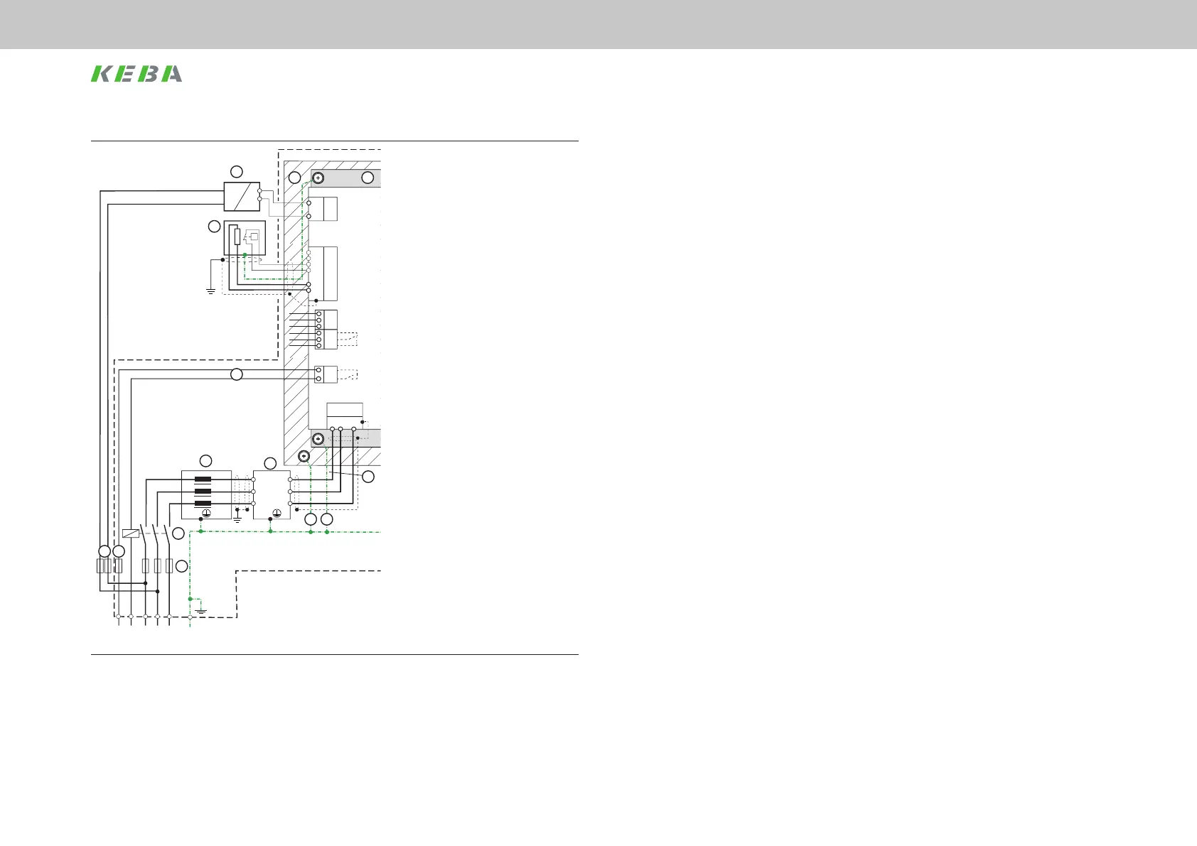
Design variants
X8
X5
L1 L3L2
1116
15
X6
24 V
GND
BR
BR
ϑ
ϑ
X2
n.c.
X5.1
X3 X3
X4
X5.2
DC Link -
DC Link+
GND
+24 V
X1
X6
TP
PE
4
8
=
≈
ϑ
L1 L2 L3 PEL1 N
L3
L2
L1
L3.1
L2.1
L1.1
1
2 25
7
6
5
L3
L2
L1
L3.1
L2.1
L1.1
3
W
U
V
X12
Motor
3~
ϑ
3
2
2
W
U
V
X14
Motor
3~
ϑ
3
2
2
W
U
V
X13
Motor
3~
ϑ
3
2
2
BRK
ϑ
Motor
17 18
Key
(1) Mains fuse for DC link supply
(2) Mains fuse for ext. switched-mode
power supply
(3) Mains contactor (optional)
(4) Switching contact for mains contactor
(5) Mains choke (accessory)
(6) Mains lter (accessory)
(7) Mains connection, power supply
(8) External switched-mode power supply
24 V DC
(11) Supply unit SO CM-P
(15) Braking resistor, ext.
(16) Backing plate
(17) Backing plate earthing
(18) Device earthing
(25) Cable protection 6 A gG
Figure 6.2 Connection example for SO CM-P.xxxx.0xxx.x
 Loading...