27
1 Electrical installation
Operation Manual Supply Unit SO CM-P BG1+2
ID no.: 1400.201B.5-00 Date: 02/2020
Electrical installation
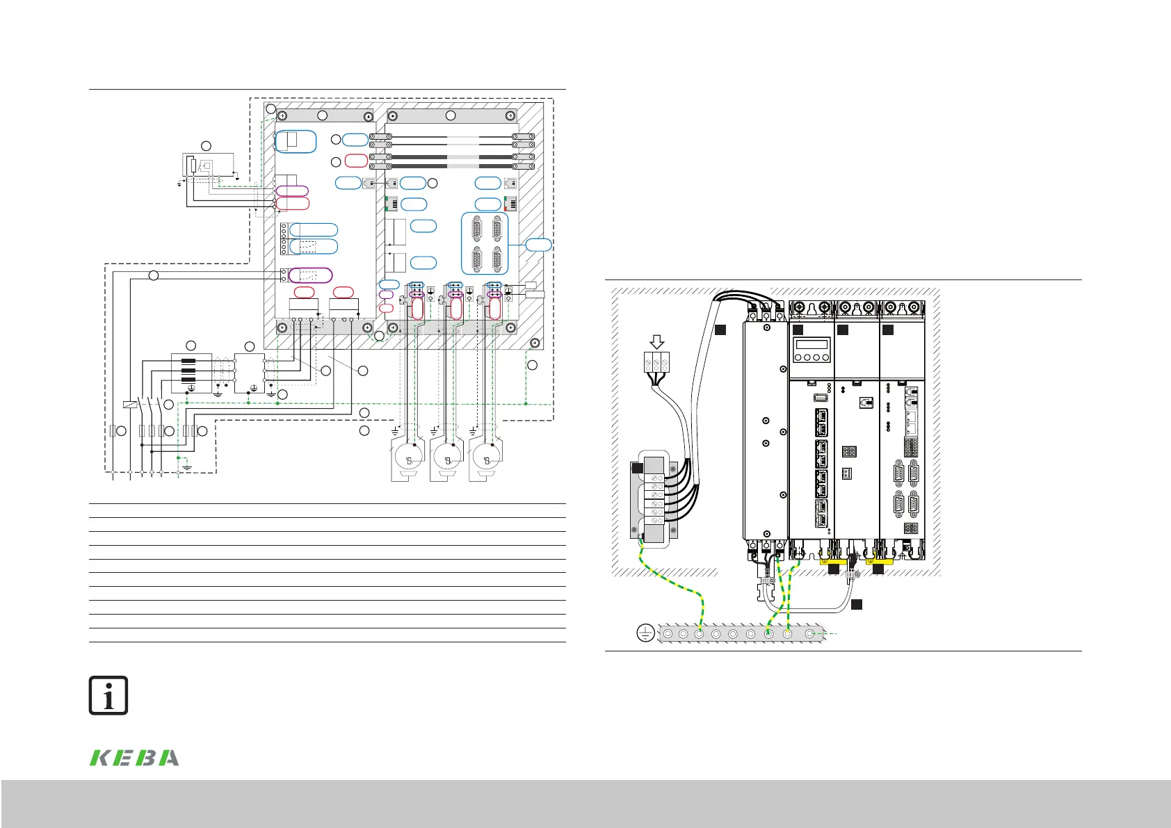
4.6 AC mains connection (power supply)
The mains connection cable is always to be laid shielded. The shield connection at the
device is made using the shield lug on the connector X8 (Line IN).
For interference suppression on the ServoOne CM system, an optimised lter from KEBA
is to be tted to the connection X8 (Line IN) on the supply unit. The supply current and
the total motor cable length must be taken into account for sizing the lter. You will nd
details in chapter "A.6 Mains lter".
Use a shielded cable to connect the mains lter to the supply unit. Connect shield at
both ends, see gure (length L ≤ 1.5 m).
5
Netz/Line
L ≤ 1,5 m
PE
1 2 3 4
6
7 7
(1) Mains lter (optional)
(2) SO MC controller
(3) SO CM-P supply unit
(4) SO CM axis controller
(5) Mains choke (optional)
(6) Cable with shield
(7) Series protective earth
conductor connection
Figure 4.7 Connection example, mains supply
At the device end, the connection is made to the shield lug on the connector X8
(Line IN). Good shielding of the connection on the mains lter can be achieved by
X6
X11
X8
X5
L1 L3L2
11
15
16
12
20
10
9
X6
X7
L1 L2
24 V
GND
BR
BR
ϑ
ϑ
X2
n.c.
n.c.
n.c.
X5.1
X3 X3
X4
X5.2
DC Link -
DC Link+
GND
+24 V
X1
X6
TP
X7
X8
X9
X10
PE
18
7 8
4
18
ϑ
PE
L3
L2
L1
L3.1
L2.1
L1.1
6
14
13
5
L3
L2
L1
L3.1
L2.1
L1.1
3
19
W
U
V
X12
Motor
3~
ϑ
3
2
2
W
U
V
X14
Motor
3~
ϑ
3
2
2
W
U
V
X13
Motor
3~
ϑ
3
2
2
BRK
ϑ
Motor
Schirmfahne
25
1 2
PELV
BI
ZK
PELV
PELV
PELV
PELV
PELV
VI
PELV PELV
PELVPELV
PELV
ZK
Netz
PELV
PELV
BI
ZK
Netz
(1) Mains fuse for DC link supply (12) Axis controller
(2) Mains fuse for switched-mode power supply (13) Switch cabinet
(3) Mains contactor (optional) (14) Panel
(5) Mains choke (accessory) (15) Braking resistor with temp. monitoring (external)
(6) Mains lter (accessory) (16) Backing plate
(7) AC mains supply (lPower) (17) Backing plate earthing
(8) AC mains supply (24 V SMPS) (18) PE protective earth conductor connection
(9) Busbars DC link (19) Series protective earth conductor connection to the next device
(10) Busbars 24 V DC (PELV) (20) Cross-communication
(11) Supply unit (25) Cable protection (6 A gG)
Figure 4.6 Electrical isolation concept overview
NOTE:
The electrical isolation concept complies with the product standard
EN 61800-5-1.
 Loading...