28
1 Electrical installation
Operation Manual Supply Unit SO CM-P BG1+2
ID no.: 1400.201B.5-00 Date: 02/2020
Electrical installation
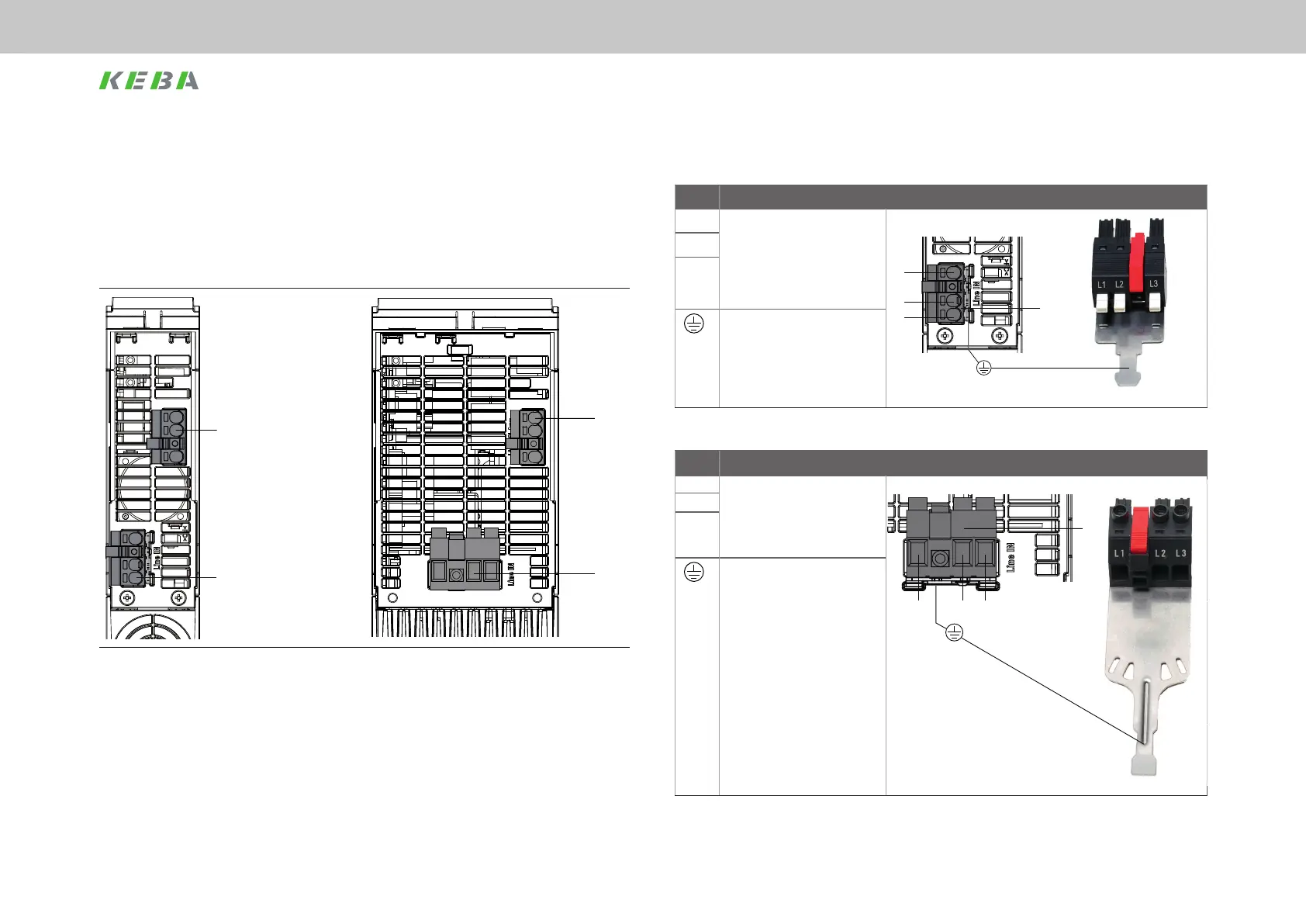
4.6.2 Connector specication
Term. Specication X8 BG1
L3 x 3 x 230 V AC
x 3 x 400-480 V AC
x Approx. 3 x 25 A current
consumption
x Connection cross-section:
6 mm
2
max.
X8
L3
L2
L1
L2
L1
x Shield lug on the connector is
only for the connection of the
cable shield (see photograph).
For ordering information on
the connector set, see note.
Table 4.4 Specication, AC mains connection X8 BG1
Term. Specication X8 BG2
L3 x 3 x 400-480 V AC
x Approx. 3 x 50 A current
consumption
x Connection cross-section:
16 mm
2
max.
X8
L1 L2
L3
L2
L1
x Shield lug on the connector is
only for the connection of the
cable shield (see photograph).
For ordering information on
the connector set, see note.
Table 4.5 Specication, AC mains connection X8 BG2
mounting the mains lter on a metal, conductive and well-grounded base plate and
the connecting the cable shield to the backing plate as close as possible to the "Load"
connection on the mains lter.
This cable can also be unshielded up to a cable length of max. 0.3 m.
4.6.1 Layout, underside X7 and X8
X7
X8
X7
X8
Figure 4.8 Layout, BG1 (underside) Figure 4.9 Layout, BG2 (underside)

 Loading...