19
Mechanical installation
Operation Manual Supply Unit SO CM-P BG1+2
ID no.: 1400.201B.5-00 Date: 02/2020
Mechanical installation
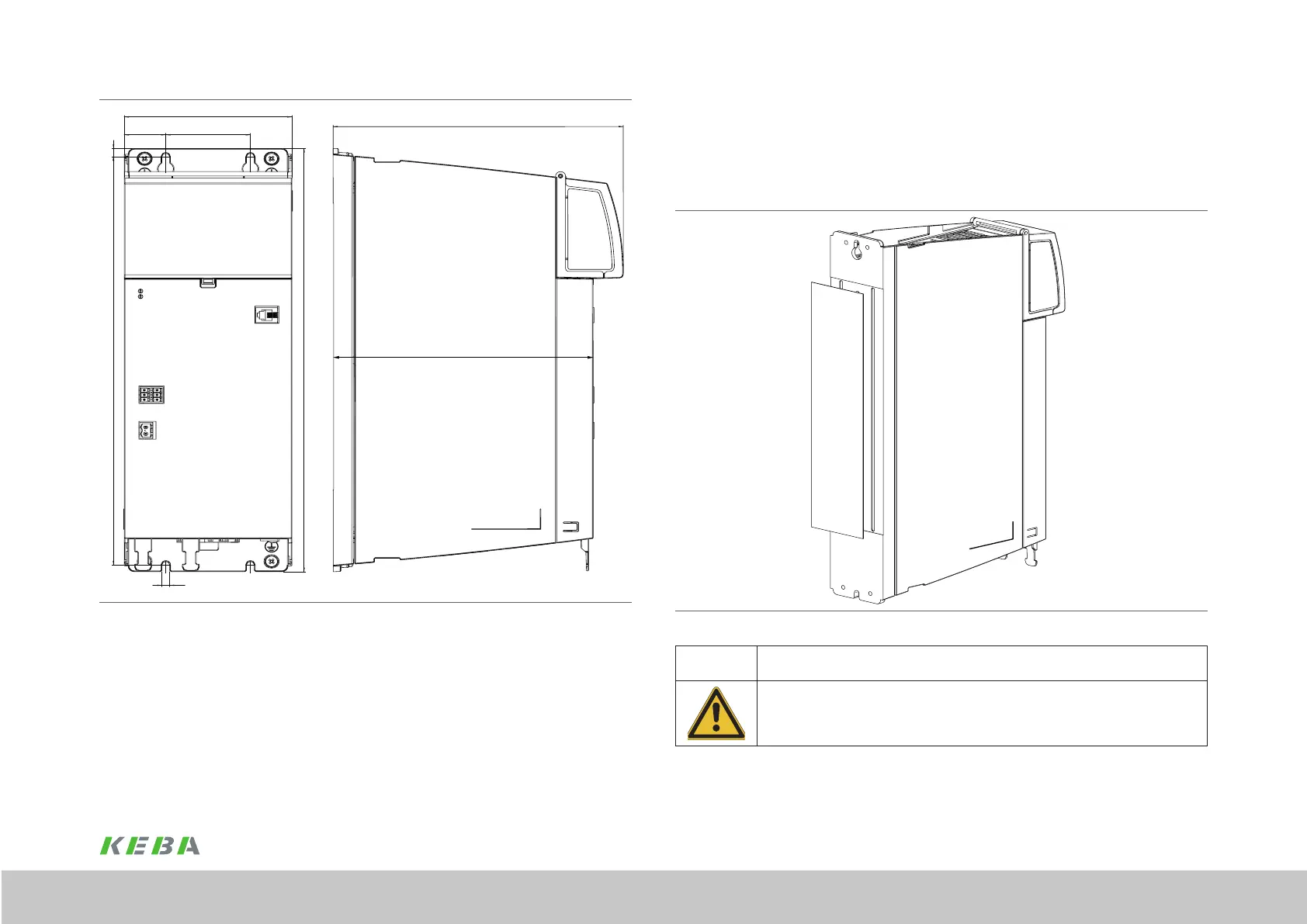
3.5.2 Installation on the cooler
For the optimal transfer of heat from the rear wall of the device to the cooler provided,
a thermally conductive lm is already bonded to the cooling plate on the device
(see Figure 3.8). The lm is laminated with aluminium toward the cooler. The device can
be mounted and also removed with the lm.
Figure 3.8 Rear wall with lm ServoOne CM axis controller BG1 (cold plate)
CAUTION! Damage to the device due to incorrect mounting!
If this instruction is not followed, the device will overheat due to the
poor thermal transfer. The device would fail as a result.
x Please ensure that there is no dirt between the cooler and the rear wall of the device during
mounting.
Figure 3.7 Dimensional drawing, ServoOne CM axis controller BG2 cold plate (see Table 3.2)
 Loading...