17
Mechanical installation
Operation Manual Supply Unit SO CM-P BG1+2
ID no.: 1400.201B.5-00 Date: 02/2020
Mechanical installation
3.5 Installation of the devices for cold plate
Step Action Comment
1.
Arrange the supply unit on the backing plate as per
Figure 3.1.
Also provide enough space to the left of the supply unit for
the MotionOne CM controller.
Align all devices in a multi-axis group in a line along the
top edge of the devices.
This action is necessary to be able to
couple the DC link using the busbars.
For information on the mounting clearances
see Table3.1.
2.
Mark out the position of the tapped holes on the cooler to
be used.
Drill holes in the cooler and cut a thread for each xing
screw in the backing plate.
Pay attention to the bending radius of the
connection cables!
For hole spacing and dimensional drawings
see Table
3.
The thermally conductive lm is already bonded to the rear
wall of the cold plate devices.
Mount the devices vertically and butt mounted in a row on
the backing plate. Tighten the screws evenly so that the
thermal resistance remains as low as possible.
Make sure the surface of the cooler is free
of drill chippings or other soiling.
Continue with the electrical installation in chapter 4.
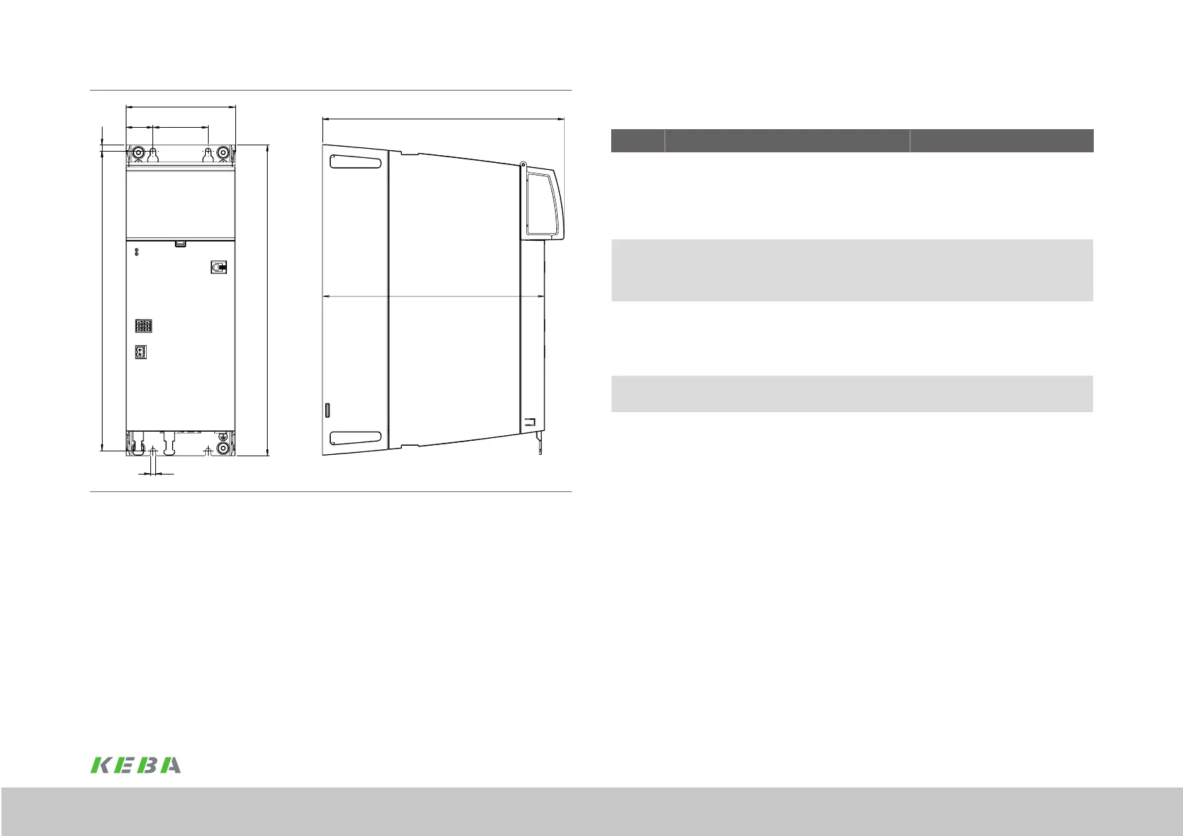
A
A1
H
C
T
T1
Figure 3.5 Dimensional drawing, supply unitBG2, for dimensions see Table 3.1
 Loading...